¶ Overview
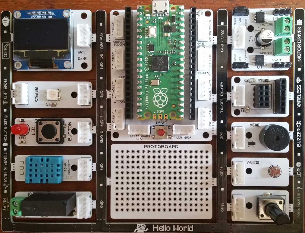
PicoBricks Library is used to drive the modules on the Robotistan PicoBricks Board.
For details of the board and how to set it up, please refer to PicoBricks Board section.
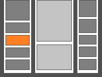
In the block descriptions below, we have used a template image of the board with the relevant component colored in orange, to designate the location of the component. This way one can easily verify the component that the block is controlling.
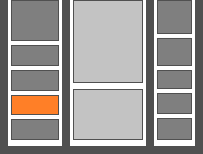
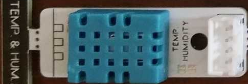
In the template picture above, the DHT sensor location is colored in orange, pointing to the blue DHT sensor on the board (second from the bottom left).
HARDWARE CHANGE NOTIFICATION:
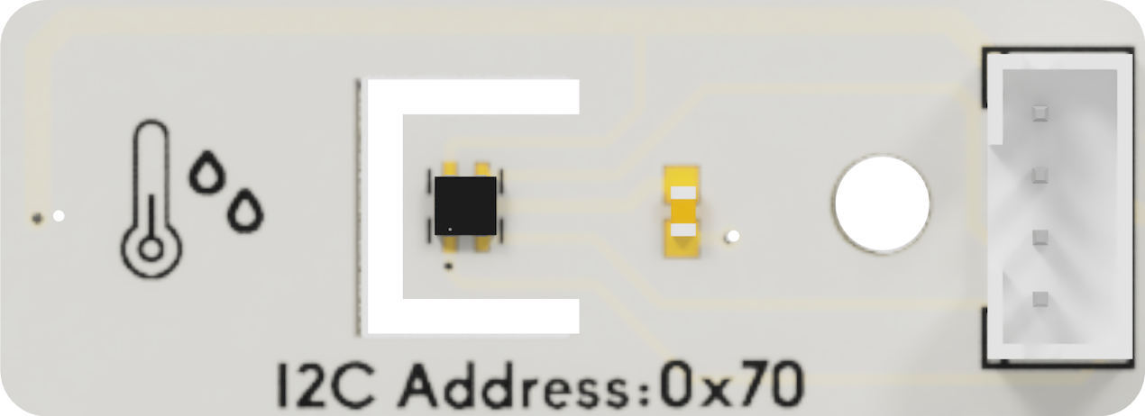
July 2024 timeframe, Robotistan introduced a change with the Temperature & Humidity Sensor and motor controller module. They have switched to I2C version of these modules, which will offer better functionality.
Corresponding changes in the MicroBlocks Library have been implemented as of version 2.7 of the PicoBricks Library.
Please refer to corresponding block descriptions below for specifics.
¶ Summary of Blocks
For each block, there is a short description entry and a detailed block and component description. You can click on block pictures in the short description table to access the details and sample codes.
Sample codes on how to use the blocks have been provided. To try them out, all you have to do is open a browser session of the MicroBlocks IDE and drag and drop them onto the editor programming area. Then you can just click on them and see the results.
To test any of the sample codes below, just drag and drop them onto the MicroBlocks IDE.
| Short Description | |
|---|---|
 |
Sets the RGB LED to the selected color. |
 |
Returns a RGB color value |
 |
Sets the RGB LED to a random color. |
 |
Turns off the RGB LED. |
 |
Returns the button status as TRUE:on FALSE:off |
 |
Sets the red LED as TRUE:on FALSE:off |
 |
Returns the humidity percentage value. |
 |
Returns the temperature in Celsius. |
 |
Sets the relay as TRUE:on FALSE:off |
 |
Makes a beep sound from the speaker. |
 |
Returns the light level as a percentage value. |
 |
Returns the potentiometer value. |
 |
Controls the DC motors (not supported) |
 |
Controls the DC motors (new) |
 |
Controls Servo motors (new) |
 |
Initializes the library pins assignments. |
 |
Checks for new i2c motor controller. |
¶ Working with Library Blocks
The library consists of a set of simple services, that together allow the user to have complete control of the PicoBricks Board and the modules on it.
PicoBricks Library has two distinct types of block shapes:
-
oval: these are reporter blocks that return some kind of information back. The user would normally either assign these to a project variable or use it in a suitable input slot of other blocks. The return information type can be any of the supported data types.
-
rectangular: these are command blocks that perform a programmed function and do not return any information.
¶ Block Descriptions
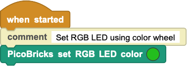
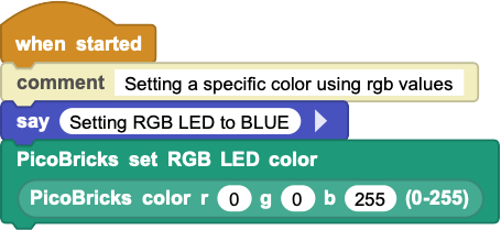
¶ PicoBricks set RGB LED color

Allows one to select a color from the color picker and set the RGB LED to that color. You can also use the PicoBricks_RGB random color or the PicoBricks_RGB color to generate colors.
¶ Sample Code
¶ PicoBricks color
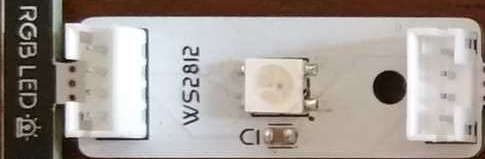
An RGB LED is a combination of 3 LEDs in just one package:
1x Red LED
1x Green LED
1x Blue LED
You can produce almost any color by combining those three colors.
RGB LED colors are set using the color picker in the set color block. However, this is not a convenient method for programmatic setting of colors.
This block will return a color code according to the R, G, B values selected. This block can be placed into the color area of the set color block.
¶ Sample Code
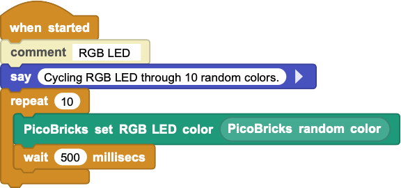
¶ PicoBricks random color
Generates a random color value that can be used in any of the RGB color inputs.
¶ Sample Code
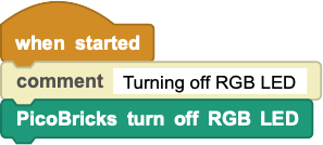
¶ PicoBricks turn off RGB LED
Turns off the RGB LED light.
¶ Sample Code
¶ PicoBricks button
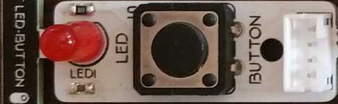
This block returns the status of the button next to the red LED.
When the button is pressed, it will return a true value; when not pressed, it will return a false value.
¶ Sample Code
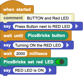
¶ PicoBricks set red LED
This is a standard single LED component of red color.
The block will allow the selection of TRUE=on or FALSE=off and set the LED accordingly.
¶ Sample Code
¶ PicoBricks humidity

HARDWARE CHANGE NOTIFICATION:
July 2024 timeframe, Robotistan introduced a change in the Temperature & Humidity sensor module. They have switched to I2C version of this module which will offer better functionality.
Corresponding changes in the MicroBlocks Library have been implemented as of version 2.7 of the PicoBricks Library.
The new blocks (PicoBricks temperature & PicoBricks humidity) introduced works automatically work with both old and new versions of the modules. However, you need to replace the old block in any of your scripts with the new block.
Both types of sensors on-board provide the ability to read the Humidity and the Temperature of the board environment.
¶ If you have the ORIGINAL version with the DHT11 module:
This sensor can measure temperature from 0°C to 50°C and humidity from 20% to 90% with an accuracy of ±1°C and ±1%.
¶ If you have the NEW version with the SHTC3 module:
This sensor covers a humidity measurement range of 0 to 100 %RH and a temperature measurement range of - 40 °C to 125 °C with a typical accuracy of ±2 %RH and
±0.2°C.
¶ Sample Code
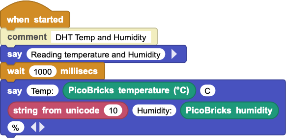
¶ PicoBricks temperature
  ;
HARDWARE CHANGE NOTIFICATION:
July 2024 timeframe, Robotistan introduced a change in the Temperature & Humidity sensor module. They have switched to I2C version of this module which will offer better functionality.
Corresponding changes in the MicroBlocks Library have been implemented as of version 2.7 of the PicoBricks Library.
The new blocks (PicoBricks temperature & PicoBricks humidity) introduced works automatically work with both old and new versions of the modules. However, you need to replace the old block in any of your scripts with the new block.
Both types of sensors on-board provide the ability to read the Humidity and the Temperature of the board environment.
¶ If you have the ORIGINAL version with the DHT11 module:
This sensor can measure temperature from 0°C to 50°C and humidity from 20% to 90% with an accuracy of ±1°C and ±1%.
¶ If you have the NEW version with the SHTC3 module:
This sensor covers a humidity measurement range of 0 to 100 %RH and a temperature measurement range of - 40 °C to 125 °C with a typical accuracy of ±2 %RH and
±0.2°C.
¶ Sample Code
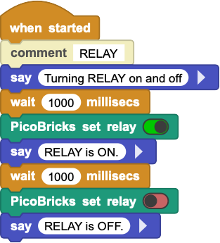
¶ PicoBricks set relay

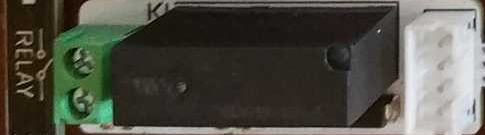
This is a relay switch, that enables one to turn the AC side switch ON or OFF by setting this block to the corresponding setting.
When set to TRUE=on (or FALSE=off) the green connectors on the component will be internally connected (or disconnected). This can be used to turn on / off any device that is connected to the green connectors.
¶ Sample Code
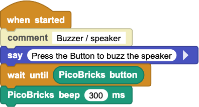
¶ PicoBricks beep

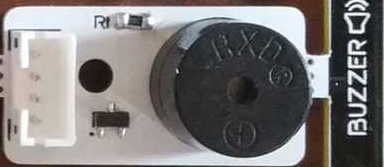
This block makes a short buzz sound via the speaker. The duration of the sound can be set in milliseconds. For a more detailed ability to control the tone functionality, please refer to the TONE Library details.
¶ Sample Code
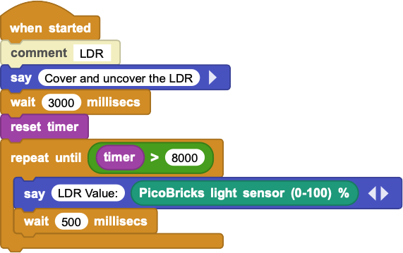
¶ PicoBricks light sensor

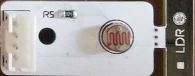
An LDR is a component that has a (variable) resistance that changes with the light intensity that falls upon it. This allows them to be used in light sensing circuits. Light Dependent Resistors (LDR) are also called photoresistors.
The values returned by this sensor are percentages proportional to the light detected. When there is almost no light, the values will be towards the low end (0). And when there is any light, depending on the type and intensity, the readings will be towards the high end (100).
¶ Sample Code
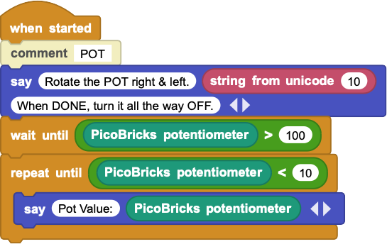
¶ PicoBricks potentiometer

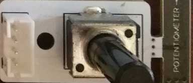
A potentiometer is an ordinary variable resistor. It functions as a potential divider, which is used to generate a voltage signal depending on the location of the potentiometer. This is the signal that can be used for a very wide variety of applications including an amplifier gain control, measurement of the distance or angles, tuning of the circuits and many more.
Potentiometers are wired as variable voltage dividers: connect +V to one side, connect the other side to ground, and the middle pin will output a voltage between 0 and +V.
In our case, the the block will return values from 0 to 1023, representing the voltage range of 0 - 3.3V.
¶ Sample Code
¶ PicoBricks set motor old
Not supported as of June/July 2024)
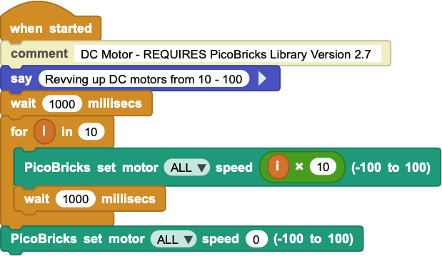
¶ PicoBricks set motor

HARDWARE CHANGE NOTIFICATION:
July 2024 timeframe, Robotistan introduced a change in the motor controller module. They have switched to I2C version of this module which will offer better functionality.
Corresponding changes in the MicroBlocks Library have been implemented as of version 2.7 of the PicoBricks Library.
The new Motor blocks (PicoBricks set motor & PicoBricks set servo) introduced works automatically work with both old and new versions of the modules. However, you need to replace the old block in any of your scripts with the new block.
The new Servo block introduced will only work with the new version of the module.
The old module operates at 5V. The new module operates at 3.3V.
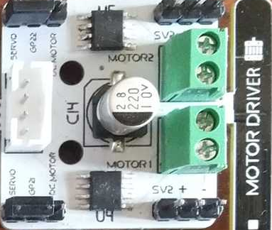
¶ If you have the ORIGINAL version of the motor controller module:
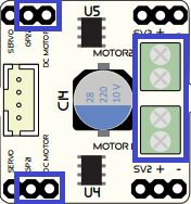
The new block will control the DC motors connected to the old Motor control module.
Please make sure to switch the jumpers on the module to the "DCMotor" position and connect the motors to the green power connectors. See blue markings in the image above.
Setting values below ZERO (0) will make the DC motors stop, since the old controller does not support bidirectional operation.
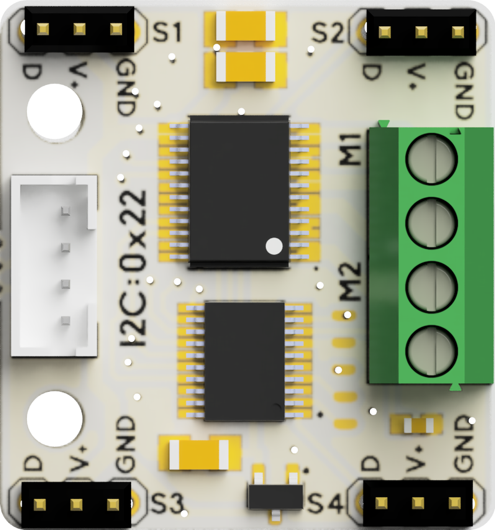
¶ If you have the NEW version of the motor controller module:
You will notice that there are no jumper pins to switch between DC and Servo support functions. The new module introduces bidirectional DC motor control and simultaneous use of both DC and Servo motors attached. By setting positive or negative values, you will be able to control the turn direction of the DC motors attached. Setting a ZERO (0) value will stop the motors.
Be aware that the motor# connection positions have changed on the new module.
¶ Sample Code
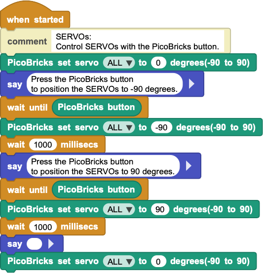
¶ PicoBricks set servo
HARDWARE CHANGE NOTIFICATION:
July 2024 timeframe, Robotistan introduced a change in the motor controller module. They have switched to I2C version of this module which will offer better functionality.
Corresponding changes in the MicroBlocks Library have been implemented as of version 2.7 of the PicoBricks Library.
The new Motor blocks (PicoBricks set motor & PicoBricks set servo) introduced works automatically work with both old and new versions of the modules. However, you need to replace the old block in any of your scripts with the new block.
The new Servo block introduced will only work with the new version of the module.
The old module operates at 5V. The new module operates at 3.3V.
The new Servo block will ONLY control the Servo motors connected to the new Motor control module.
¶ If you have the ORIGINAL version of the motor controller module:
You cannot control Servos attached to the old motor control module using this block. You need to use the SERVO Library and its blocks for that. Refer to PicoBricks Servo and DC Motor Control for details.
¶ If you have the NEW version of the motor controller module:
The new controller module introduces support for four Servos, as well as continuous servos.
For all servo motors, except the continuous servos, the angles set will be in the range of the supported degrees of motion.
For continuous servos, -90 to -1 degrees will be COUNTER-CLOCKWISE rotation and 1 to 90 will be CLOCKWISE rotation, at varying speeds. ZERO (0) degrees will stop the servo.
¶ Sample Code
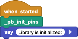
¶ _pb_init_pins
PicoBricks Board components are pre-assembled and wired via the printed circuit board they are mounted on. Therefore their connections to the pico processor is predetermined by the manufacturer of the board. As long as you do not break off the components and reassemble them to your liking, the pins assignments to drive them is as specified in this block.
This block will record the pin assignments for all other blocks to use.
If you break off / seperate the components and rewire them to other pin locations, you can change the assignments in this block and continue using the library.
¶ Sample Code
¶ _pb_new_controller
July 2024 hardware module change introduced new modules that operate on i2c protocol.
This internally used block checks to see if the new modules are in use and returns true if so.
¶ Notes on Library Components
PicoBricks board contains ten components premounted. The Library, however, only has blocks for seven of them; the OLED screen, Motor Control, and Wireless Comm components are not directly covered by the library.
In this section, we will describe how one can make use of these components, as well as some special information about them.
¶ OLED Display
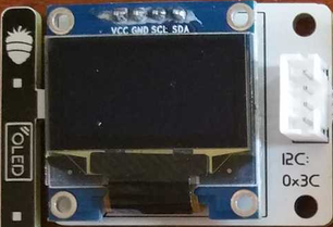
There are two ways to program the OLED display module:
- by using the MicroBlocks graphics library called OLED Graphics. It is located under Libraries+ / Graphics / OLED Graphics in the IDE.
- by using the MicroBlocks graphics library called TFTs. It is located under Libraries+ / Graphics / TFT in the IDE.
For details of the OLED library blocks and operations, refer to OLED Library. OLED and TFT blocks are very similar in functionality. Familiarity with one will assist in understanding the other.
For a project that describes advanced use of the library and data transfer, please refer to SNAP to MicroBlocks.
NOTE:
The main differences between the two libraries are as follows:
- OLED library size is 26K, TFT size is 3K
- OLED cannot adjust text sizes, TFT can
- OLED only works with monochrome SD1306 and SD1309 displays, TFT blocks will function with displays that support color
- OLED supports 5x5 sprite use, TFT does not
- OLED supports fully buffered graphics and text composition, TFT does not
- OLED supports columnar text composition, TFT does not
- OLED supports inverse text and graphics, TFT does not.
¶ MOTOR Module
HARDWARE CHANGE NOTIFICATION:
July 2024 timeframe, Robotistan introduced a change in the motor controller module. They have switched to I2C version of this module which will offer better functionality.
Corresponding changes in the MicroBlocks Library have been implemented as of version 2.7 of the PicoBricks Library.
The new Motor blocks (PicoBricks set motor & PicoBricks set servo) introduced works automatically work with both old and new versions of the modules. However, you need to replace the old block in any of your scripts with the new block.
The new Servo block introduced will only work with the new version of the module.
The old module operates at 5V. The new module operates at 3.3V.
¶ Old version of the Motor Controller Module
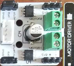
This module is used to control SERVO motors and DC motors.
SERVO motor programming is supported via the MicroBlocks library Servo. It is located under Libraries+ / Servo.ubl in the IDE.
DC Motor support is provided in the library directly. However, there is a caveat: since the motor controller is NOT a H-bridge type controller, it is not possible to programmatically reverse the direction of the DC motors.
The only way to change the direction of the DC motors is to change the way the wires are connected.
The old PicoBricks set motor block is no longer supported. Instead, there are two new blocks introduced: PicoBricks set motor and PicoBricks set servo. Refer to block descriptions above for details.
For a detailed project that uses the DC and Servo motors, please refer to PicoBricks Servo Motor Control.
¶ New version of the Motor Controller Module
This module is used to control two DC and four Servo motors. It provides the capability to reverse the DC motor direction.
The old PicoBricks set motor block is no longer supported. Instead, there are two new blocks introduced with version 2.7 of the library: PicoBricks set motor and PicoBricks set servo. Refer to block descriptions above for details.
¶ WIRELESS COMM Module
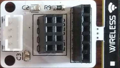
This module enables PicoBricks to communicate with other environments using either a WIFI module or a Bluetooth module and is connected to the Serial IO ports of the Pico.
¶ WIFI
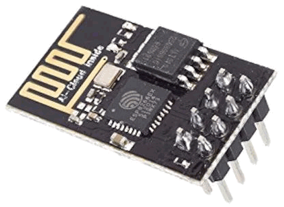
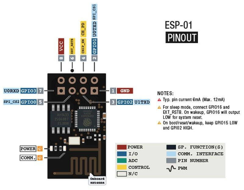
The specific WIFI module supported is the ESP01 (ESP8266). This is very small form-factor unit that is programmed using the AT command set.
¶ Bluetooth
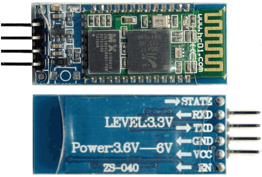
Likewise, the Bluetooth modules supported can be any one that is programmed via the AT command set. Most popular ones are the HC-05 or HC-06 units.
Both communications options are programmed using the AT command sets of the specific boards. Since the AT programming is done over the Serial comm port of the processor, the command blocks to do that are already present in the MicroBlocks.
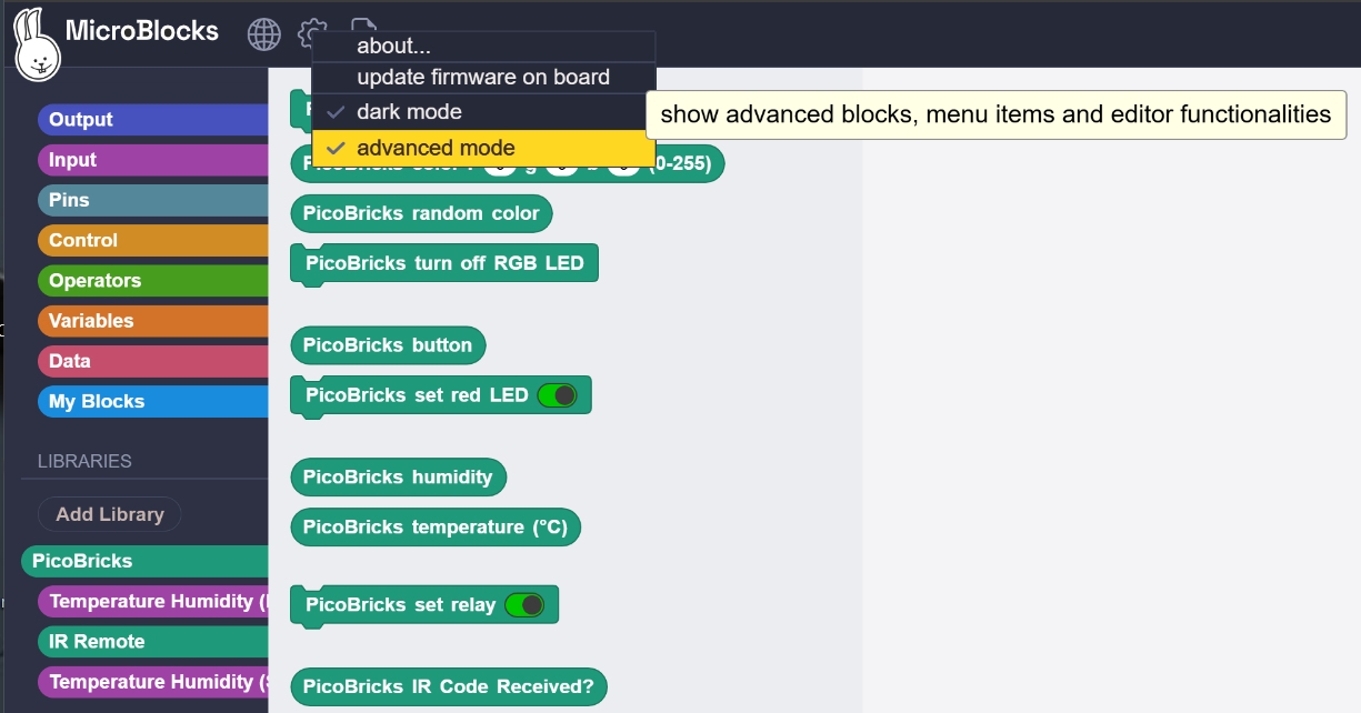 |
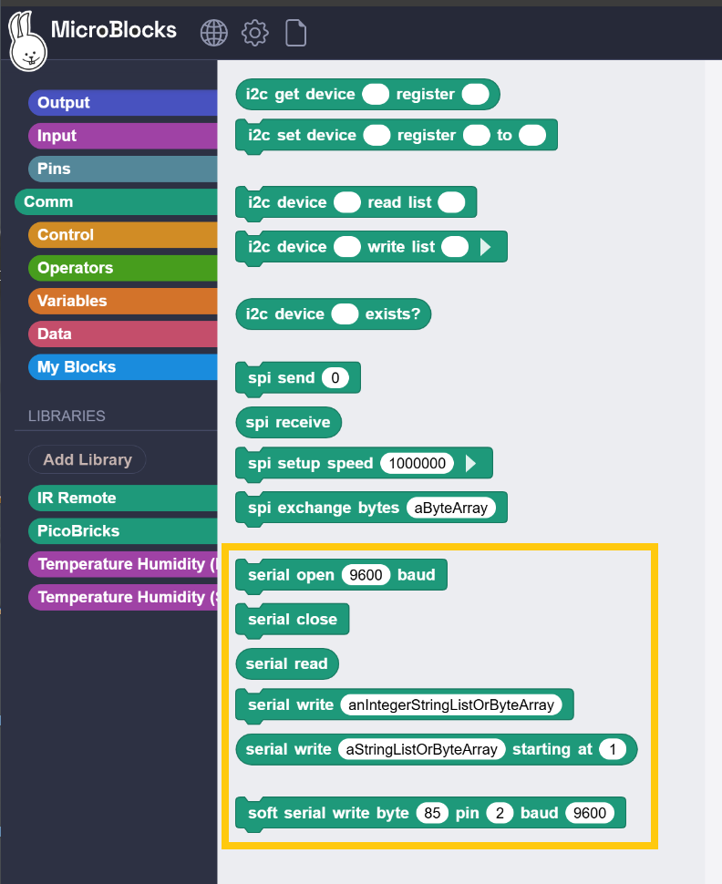 |
|---|
Simply enable the advanced mode option under the MicroBlocks (Gear) in the menu. This will display the Comm blocks category. Within you will find the Serial set of blocks.