¶ Overview
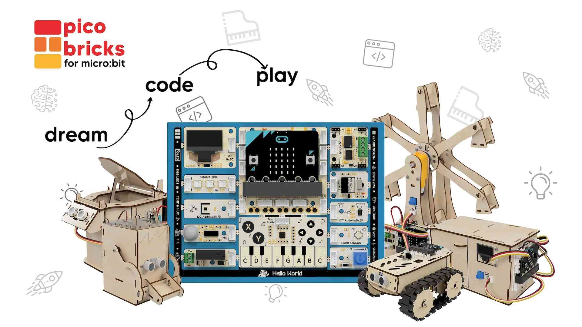
The PicoBricks micro:bit is a special board, built by Robotistan for the education sector, combining a micro:bit and eleven different components on a prewired circuit board design.
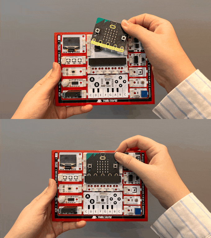
A key advantage of this design is that all the components are prewired, so a beginner can start by exploring and coding the components without first doing any wiring. For learners just getting started with electronics, this approach removes the possibility of making frustrating wiring errors, allowing them to be successful from the start. Later, as they grow in confidence and experience, the learner can break apart the board and build selected components into projects.
In short, the PicoBricks micro:bit board combines the benefits of an all-in-one microcontroller board like the micro:bit with the flexibility of a simple board plus a kit of parts.
¶ PicoBricks micro:bit Modules
The board incorporates the following modules on its circuit board:
- Main board with edge connector mounted micro:bit with 11 Grove connectors
- Monocrome 128 x 64 OLED (SDD1306)
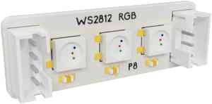
- 3 x RGB LED (WS2812)
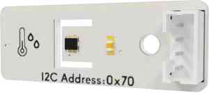
- Temperature and humidity sensor (SHTC3)
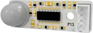
- IR Motion (PIR)
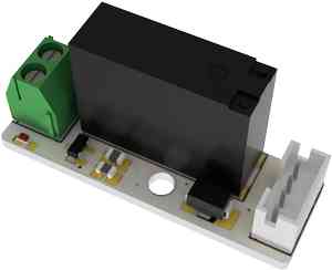
- Relay switch (can switch 5V-250V 5A)
- 14ch TOUCH Panel (CY8CMBR3116)
- Potentiometer and Button
- Light sensor
- Light & Gesture (APDS9960)
- Combination WIFI and IR sensor
- 2 x DC & 4 x SERVO Motors (HK32F030)
All components are mounted on separate circuit board units attached to the main circuit board and connected to the micro:bit microprocessor via PCB traces. Each unit can be broken off and used individually. Each unit and the main board also incorporate Grove connectors that are used to connect to the module boards after they have been broken-off. There is also a battery connector to power the board without any USB cables..
MicroBlocks has a library for this board. See PicoBricks-mb Library Guide for details.
Following is a table describing the modules provided with this board.
 |
 |
 |
 |
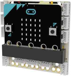
| micro:bit this main module provides cableless connectivity to all other modules. |
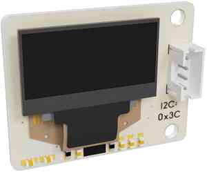
OLED (v2 only) 128x64 monochrome display can be used to output values from other sensors. |
3xRGB this small neo-pixel strip can be used to create color combinations by mixing rgb values of 0-255. |
Temp & Humidity Senses environmental temperature and humidity. |
 |
 |
 |
 |
| PIR passive IR sensor detects movement within its vicinity. |
Relay Can be used to switch on/off electric devices based on events and sensor values. |
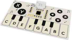
Touch Provides tactile sensing for 2 buttons, four arrows, and a keyboard section. |
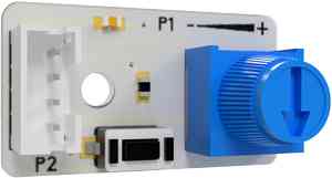
Pot & Button Potentiometer provides analog values 0-1023. Button triggers on/off value. |
 |
 |
 |
 |
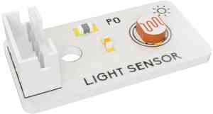
| Light Detector Provides ambient light values in the range of 0-100%. |
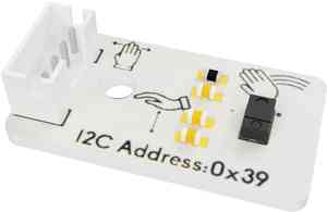
Gesture allows detection of hand movements in four directions, up/down proximity, and color values of objects nearby. |
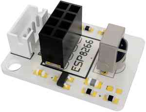
WIFI (v2 only) & IR Sensor IR sensor can decode remote control buttons. ESP01 WIFI can be used to create IoT projects. |
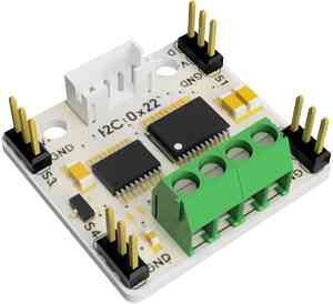
Motor Control (with battery) Drives 2xDC and 4xServo motors. |
 |
|||
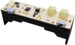
| 18650 Li-Ion Battery & Charger Used to provide ample power for the motor module and untethered operation of the card. |
¶ micro:bit Pinouts
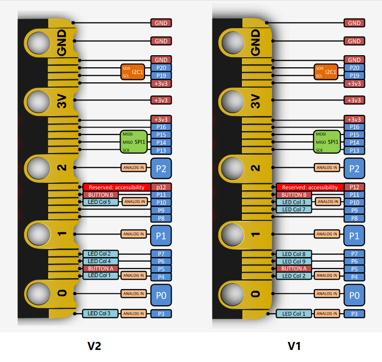
PicoBricks micro:bit kit can be used with either micro:bit versions, v1 or v2. However, some hardware features (e.g. OLED display and WiFi) are not supported with the v1 version, and thus cannot be used. For most flexibility and feature rich applications, prefer micro:bit v2.
The MicroBlocks firmware for the micro:bit boards uses the default pin assignments shown above for the I2C (P19-20) and SPI (P13-15) functions. Those pins can be also used as general purpose digital pins when the I2C and SPI functions are not in use.
micro:bit microcontroller's hardware features are automatically supported in MicroBlocks by uploading the micro:bit firmware and specific libraries.
OLED and TFT display is only supported in micro:bit v2.
UART support is only available on micro:bit V2, and is normally on pins (P0-1). However, since these two pins are in use by other modules on the PicoBricks board, we have rerouted the Serial port functionality to pins P14-15.
Wireless module (ESP01) is accessed via the Serial port capability, and therefore is only supported in micro:bit v2. It shares pins P14-15 with the IR sensor. Therefore, only one of them at a time can be used in the same program.
Note:
This SERIAL PORT change to P14/15 is valid only in the context of the PicoBricks micro:bit Library.
If you are using a micro:bit v2 microcontroller without the PicoBricks board, then normal pin assignments apply.
Please refer to special pins for a comprehensive pin assignment information.
¶ Power Connections
micro:bit microcontroller needs to be installed into the edge connector socket located on the PicoBricks board.
Once in, it can either be powered three different ways:
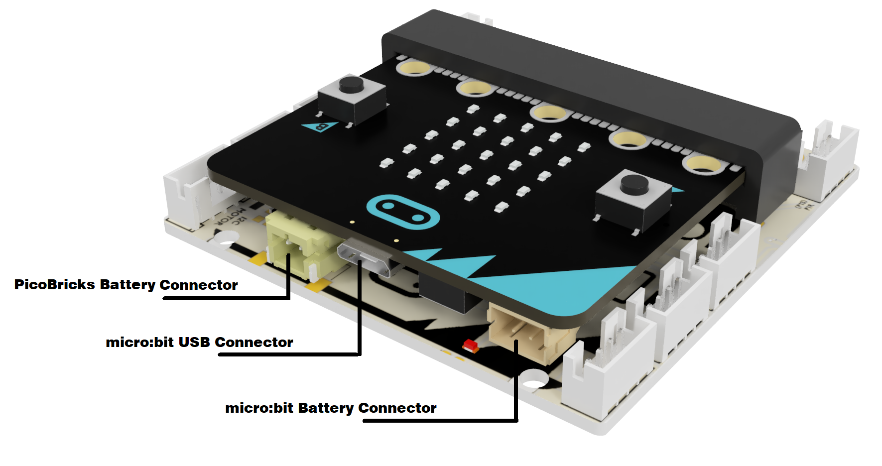
1. by a USB cable that can be connected to its USB port on top.
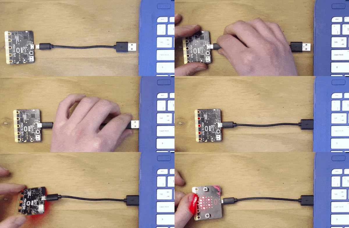
This will be the most common connection mode, as well as the required mode of connection for programming the board. Please note that even though this connection provides a 5V power to the micro:bit microcontroller, it may not prove enough if the motor controller is used with a large number of DC motor and Servos attached. The usual power profile of the micro:bit ports are not sufficient to drive the full load of motor components.
NOTE:
Make sure to use the PicoBricks Battery connector to drive full set of DC motors and servos attached to the motor controller.
2. using a battery pack containing 2 x zinc or alkaline AAA batteries, connected to the micro:bit battery connector.
After viewing the video, click BACK to return to the WIKI
This mode of connection will normally be used after the micro:bit is programmed and you want to operate it in a stand-alone mode, not attached to the PC that you used to program it. Remember to heed the caution regarding the motor controller described in the USB connection mode above.
3. using the PicoBricks battery pack, connected to the PicoBricks battery connector.
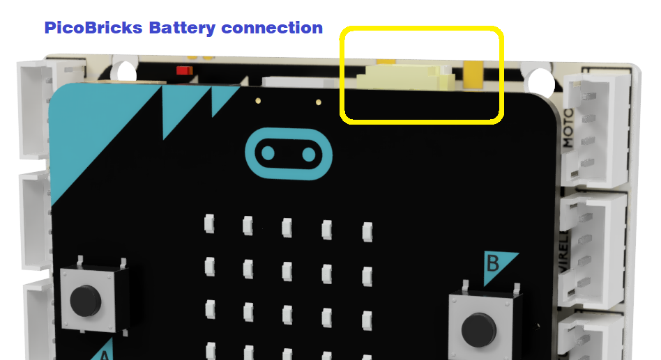
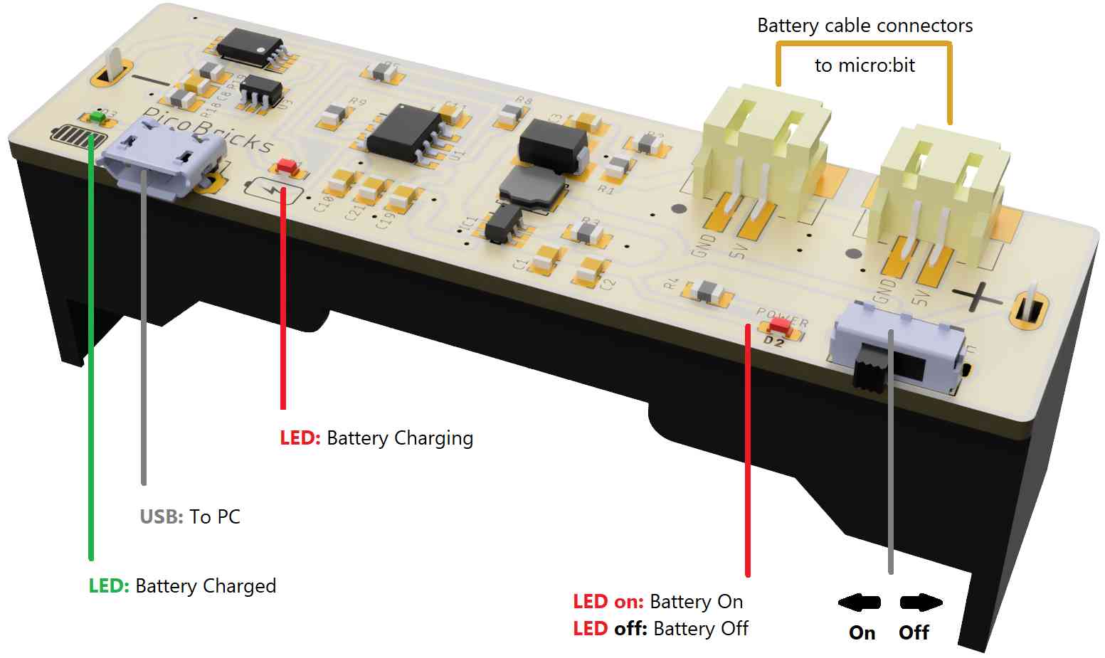
While very similar to the micro:bit battery connection described above, this battery connection mode provides sufficient power to drive all the components on the board, including the motor controller and any attached motors and servos. For a fully untethered operation experience, use this mode.
Picture above identifies all the connectors and LEDs on the PicoBricks battery module. Notice the USB connector: it is used to connect the battery module to the PC or another power source to charge the battery. The charging status will be displayed using the two LEDs. This USB connection to the PC cannot be used to program the PicoBricks micro:bit microcontroller.
Remember that to program the micro:bit, you will always have to use the USB cable attached to the micro:bit to communicate with the MicroBlocks IDE. Once programmed, you can detach the USB cable and operate only on the PicoBricks battery connection, if desired.
¶ Demo programs:
¶ Demo Program for micro:bit v2
This demo programs exercises most of the components of the PicoBricks micro:bit v2 board. It is also a good demonstration of the Parallelism feature of Microblocks. Various event handlers are running in parallel and monitoring and displaying the results of the sensor readings to the OLED display, while a PBmb message is cycling on the micro:bit's own LED display.
IR Remote and PIR Sensor components have not been included due to the following reasons:
IR Remote: This library has very time critical operations that get affected when combined with demo program's parallel scripts. Therefore, we have provided a separate demo program for this sensor, controlling the motors and servos.
PIR Sensor: This sensor senses motion in the larger vicinity of the unit and triggers a signal. When used in demo context, it generates too many unwanted triggers that hinder the rest of the demonstration. Users are encouraged to write their demo programs to that use this sensor as they see fit.
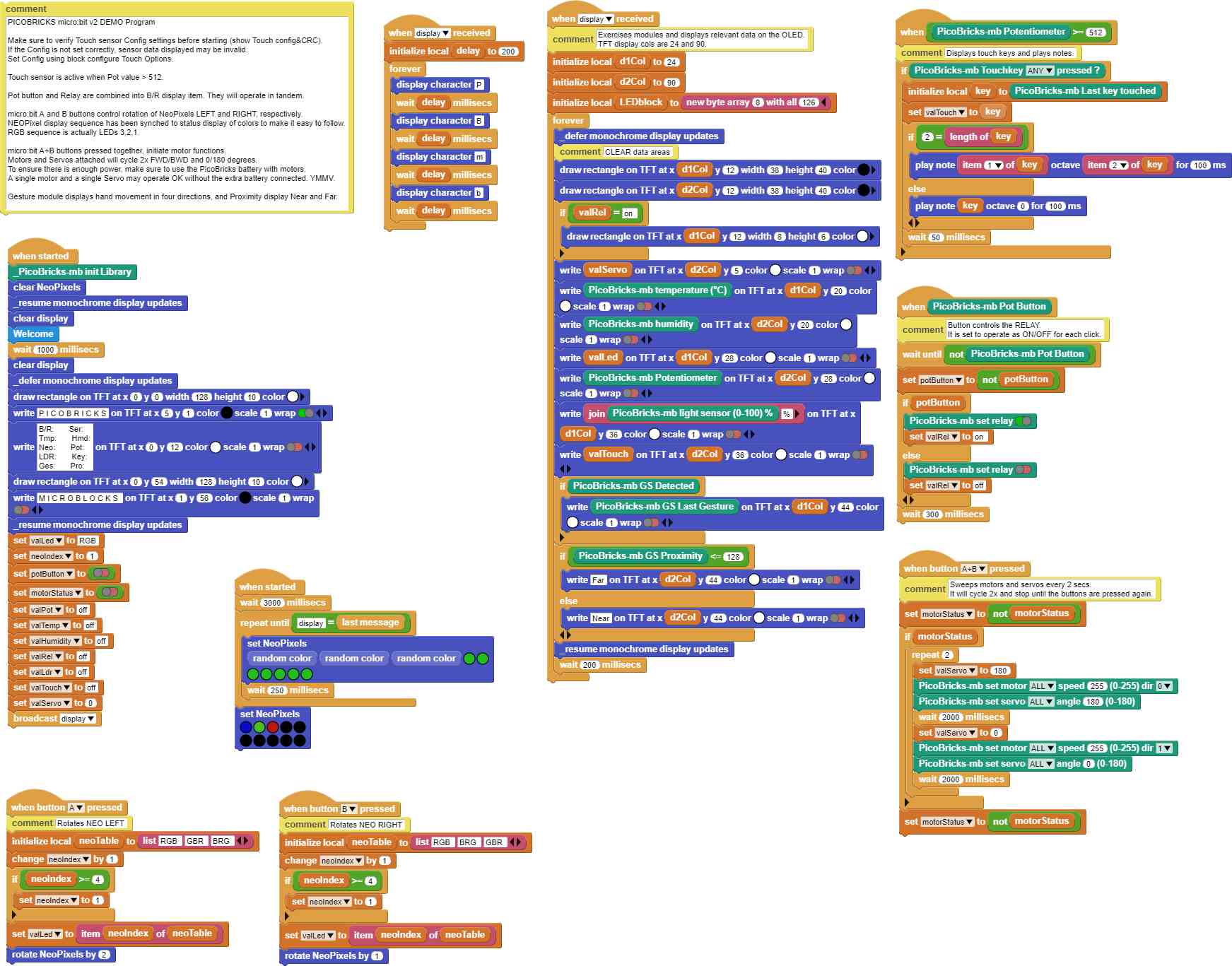
Make sure to verify Touch sensor Config settings before starting the demo. You can use the  block to do that. If the Configuration is not set correctly, sensor data displayed may be invalid. You can set / change the Touch sensor configuration using the block
  .
.
Below is a picture of the Demo program display on the OLED module.
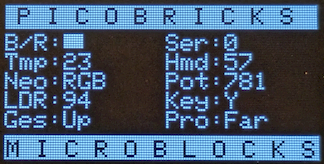
B/R: shows combined Pot button and Relay status.
They will operate in tandem. When the button next to the Pot is clicked, the Relay will switch on / off.
Ser: will display the Servo degrees, when the motor controller is engaged.
Tmp: and Hmd: display the temperature and humidity readings measured by the SHTC sensor.
Neo: displays the status of the three RGB LEDs.
micro:bit A and B buttons control rotation of NeoPixels LEFT and RIGHT, respectively. As the LED colors rotate, the display will show their respective color sequence.
Pot: displays the Pot values set using the Pot knob.
Turning the pot knob will change the values displayed 0-1023.
In the demo, Pot values control the Touch Sensor operations: Pot <= 512 disabled, Pot >512 enabled.
LDR: displays the Light sensor values detected in the range of 0-100%.
Uncovered values will be high, and covered ones low.
Key: displays the Touch sensor events detected.
In the demo, Touch sensor is controlled by the Pot values: Pot <= 512 disabled, Pot >512 enabled.
Any of the labeled keys on the sensor will be shown when touched. Touching the keyboard keys will sound the corresponding musical notes.
Ges: displays the hand motions detected by the Gesture sensor.
Basically, four directional moves will be shown: Up, Down, Left, Right.
Pro: Gesture sensor also has the ability to display the Proximity of a hand over the sensor.
As one moves a hand up and down on the sensor, the relative distance is shown as Far and Near.
micro:bit A+B buttons pressed together, initiate motor functions. Motors and Servos attached will cycle 2x FWD/BWD and 0/180 degrees. Motors will stop after two cycles of operation.
To ensure there is enough power, make sure to use the PicoBricks battery with motors.
A single motor and a single Servo may operate OK without the extra battery connected. YMMV.
¶ PicoBricks micro:bit Demo Program - IR Remote controlling Motors and Servos
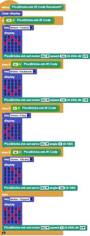
This demo program demonstrates control of the DC motors and Servos using an IR Remote Controller. It can be used with both micro:bit v1 and v2.
 |
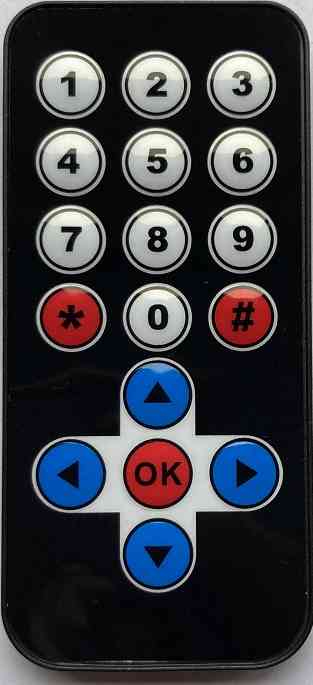 |
Four directional buttons of the remote controller are used as listed below: up / down: drives DC motors forwards and backwards left / right: makes servos move 0 and 180 degrees. any other key: stops DC motors. |
|---|
NOTE:
Due to the time critical operational requirements of the IR Remote Library, users should be mindful of combining this operation with other simultaneous operations in a MicroBlocks program.
¶ DOWNLOADS
PicoBricks micro:bit v2 Demo Program
PicoBricks micro:bit Demo Program - IR Sensor controlling Motors and Servos
NOTE:
For best demonstration of the PicoBricks micro:bit board, please run the micro:bit v2 specific version of the demo program.
