¶ Overview
PicoBricks-mb library is used to drive the modules on the Robotistan PicoBricks-mb Board. This board is the new member of the PicoBricks family and it features support for the micro:bit microcontrollers.
For details of the board and how to set it up, please refer to PicoBricks-mb Board section.
In the block descriptions below, we have used a template image of the board with the relevant component colored in orange, to designate the location of the component. This way one can easily verify the component that the block is controlling.
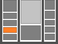
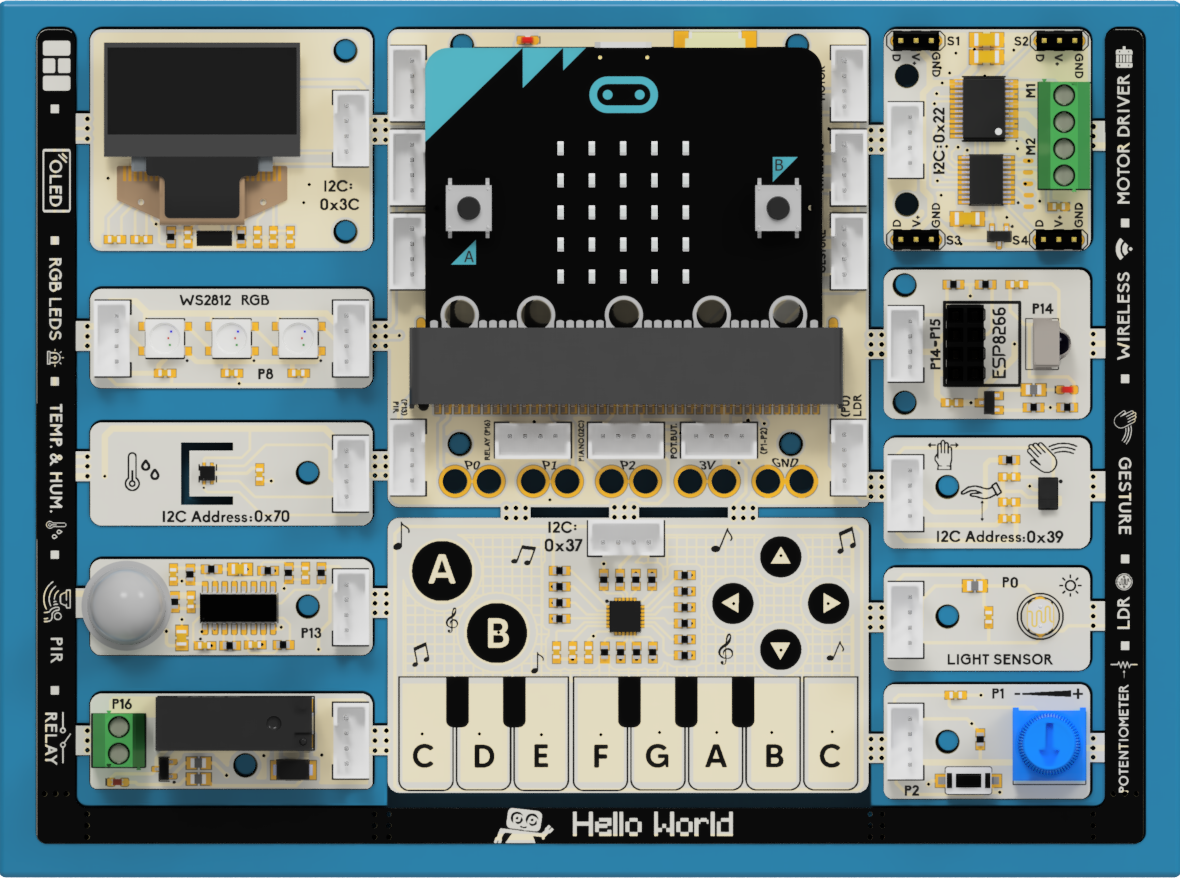
In the template picture above, the PIR sensor location is colored in orange, pointing to the white PIR sensor on the board (second from the bottom left).
¶ Summary of Blocks
For each block, there is a short description entry and a detailed block and component description. You can click on block pictures in the short description table to access the details and sample codes.
Sample codes on how to use the blocks have been provided. To try them out, all you have to do is open a browser session of the MicroBlocks IDE and drag and drop them onto the editor programming area. Then you can just click on them and see the results.
To test any of the sample codes below, just drag and drop them onto the MicroBlocks IDE.
¶ Working with Library Blocks
The library consists of a set of simple services, that together allow the user to have complete control of the PicoBricks Board and the modules on it.
PicoBricks Library has two distinct types of block shapes:
-
oval: these are reporter blocks that return some kind of information back. The user would normally either assign these to a project variable or use it in a suitable input slot of other blocks. The return information type can be any of the supported data types.
-
rectangular: these are command blocks that perform a programmed function and do not return any information.
¶ Block Descriptions
¶ PicoBricks-mb beep


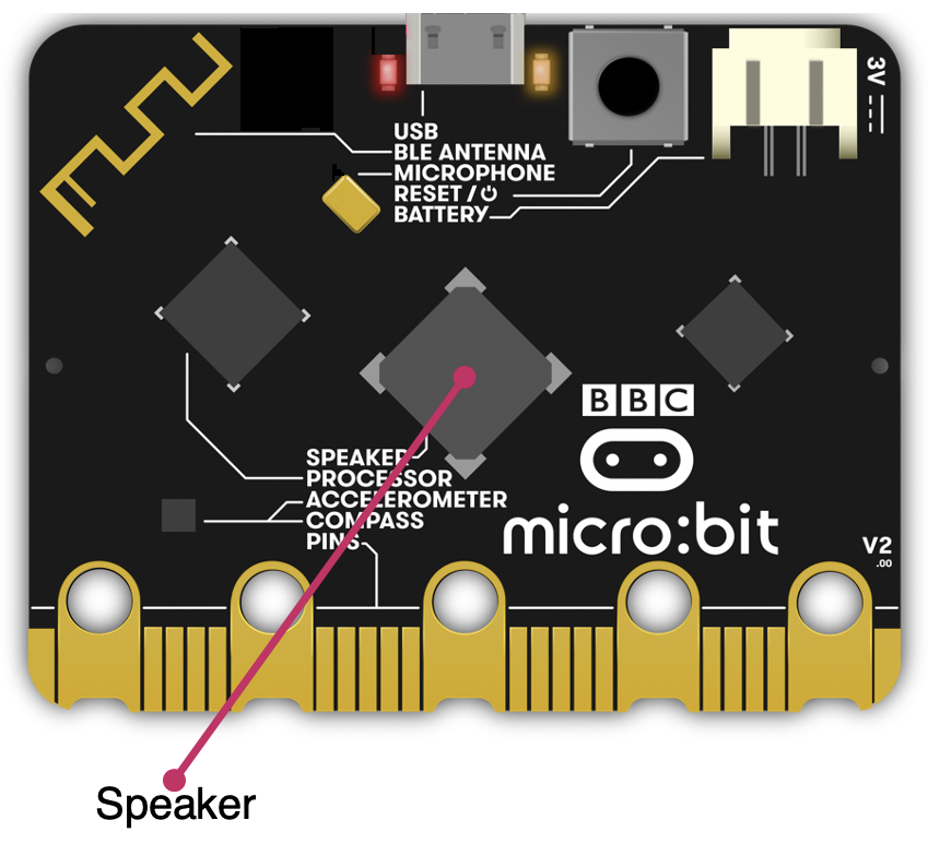 micro:bit v2
This block makes a short buzz sound via the micro:bit v2 speaker. The duration of the sound can be set in milliseconds. For a more detailed ability to control the tone functionality, please refer to the TONE Library details.
¶ Sample Code
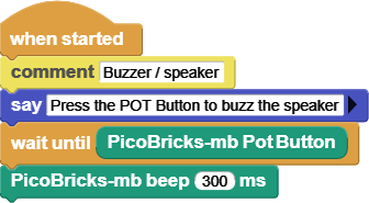
The example waits until the button next to the Potentiometer is pressed, an then makes a beep sound of 300ms duration.
¶ PicoBricks-mb humidity


 micro:bit v1, v2
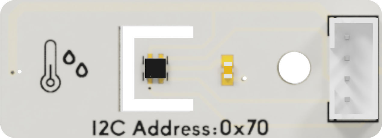
The on-board SHTC3 sensor provides the ability to read the Humidity and the Temperature of the board environment. The sensor covers a humidity measurement range of 0 to 100 %RH and a temperature measurement range of - 40 °C to 125 °C with a typical accuracy of ±2 %RH and ±0.2°C.
¶ Sample Code
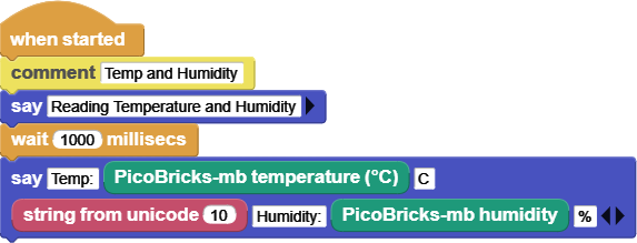
The example is for both the humidity and temperature readings of the sensor.
¶ PicoBricks-mb temperature


 micro:bit v1, v2
The on-board SHTC3 sensor provides the ability to read the Humidity and the Temperature of the board environment. The sensor covers a humidity measurement range of 0 to 100 %RH and a temperature measurement range of - 40 °C to 125 °C with a typical accuracy of ±2 %RH and ±0.2°C.
¶ Sample Code
The example is for both the humidity and temperature readings of the sensor.

¶ PicoBricks-mb PIR detected


 micro:bit v1, v2
PIR stands for Passive Infrared Sensor. PIR is an electronic sensor which detects the changes in the infrared light across certain distance and gives out an electrical signal at its output in response to a detected IR signal. It can detect any infrared emitting object such as human beings or animals if it is the range of the sensor, or moves away from the range, or moves within the range of the sensor.
This sensor will return True if any motion is detected.
¶ Sample Code
When block is used to detect events; in this case the PIR sensr readings.
When motion is detected, the script says so.

¶ PicoBricks-mb set relay


 micro:bit v1, v2
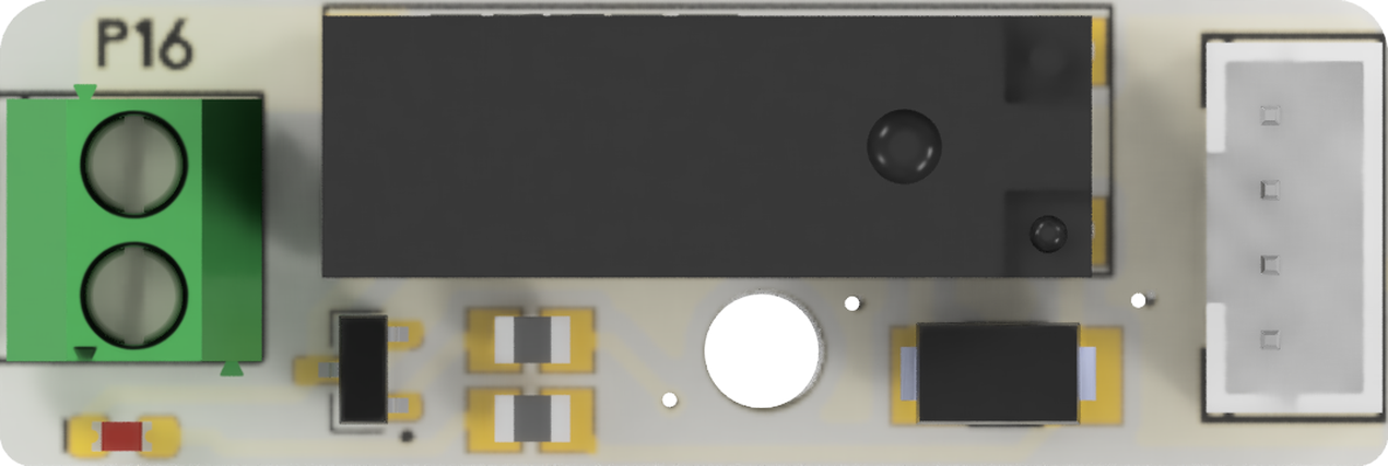
This module is a relay switch. It enables one to turn the AC side switch ON (true) or OFF (false) by setting this block to the corresponding setting.
When set to TRUE=on (or FALSE=off) the green connectors on the component will be internally connected (or disconnected). This can be used to turn on / off any device that is connected to the green connectors.
¶ Sample Code
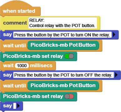
The relay is controlled by the button next to the Potentiometer.
¶ PicoBricks-mb set motor


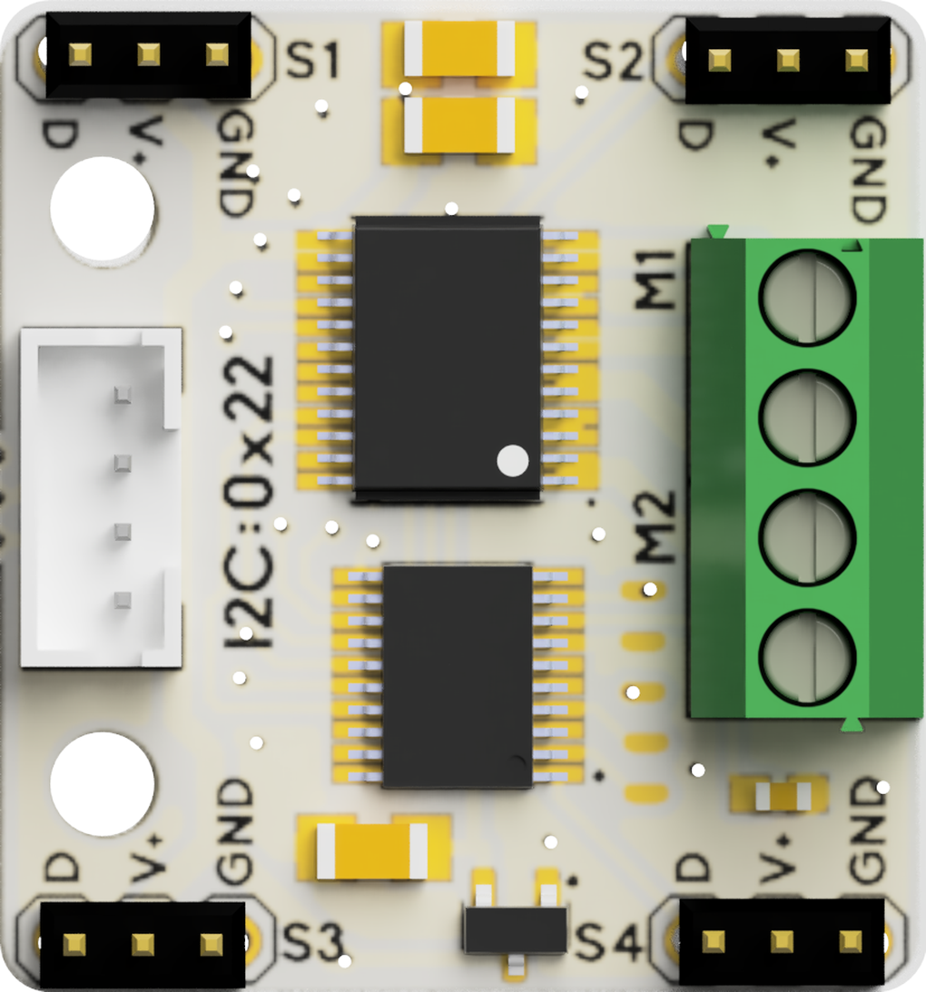 micro:bit v1, v2
Motor module controls the two DC motors (M1, M2) and four servos (S1, S2, S3, S4) connected to the Motor control module. Please refer to Motor Control Module for a detailed description of functionalities.
DC Motor Connections:
Connect the DC motors to the green power connectors.
On the four green connectors, inside connectors are Power, and outside connectors are Ground. This setup will make the two DC motors turn forward, provided they are mounted opposite of each other, as in a car.
If the motor rotations are not what you expect, you can reverse the red & black cable connections. Remember to coordinate your connectivity with the directional control provided on the block itself.
¶ Sample Code
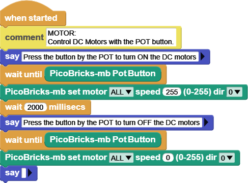
DC motors connected to the motor controller module are turned ON and OFF based on the button next to the Potentiometer.
¶ PicoBricks-mb set servo


 micro:bit v1, v2
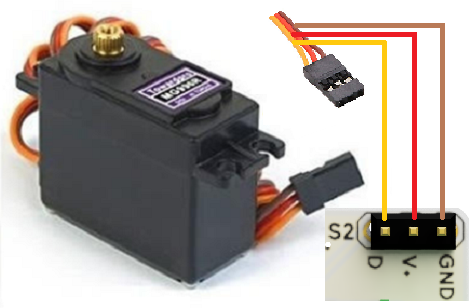
Motor module controls the two DC motors (M1, M2) and four servos (S1, S2, S3, S4) connected to the Motor control module (see picture below). Servo motors operate between the ranges of 0 - 180 degrees.
SERVO Connections:
Connect the SERVOs to the 3-pin servo connectors as shown below:
Yellow: PWM signal
Red: Power
Brown: Ground
¶ Sample Code
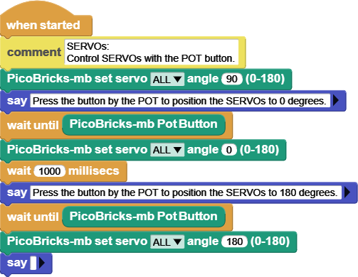
SERVO motors connected to the motor controller module are positioned to the middle setting of 90 degrees. Then they are positioned at 0 and 180 degrees per the Potentiometer button press.
¶ PicoBricks-mb IR code received


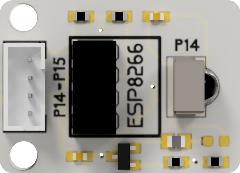 micro:bit v1, v2
Refer to IR Remote Information for technical details of this sensor.
This block waits until IR code is received, and then returns TRUE. This means that once engaged, one has to press a button on the IR remote controller for this code to continue. When a button is pressed and an IR code is received, the IR code button below can be used to retrieve the actual IR code.
¶ Sample Code
IR Code example uses all the IR related blocks in the same script.
Two different event scripts are provided:
- the first one waits for an IR code detection and then displays the code.
- the second one also waits for an IR code detection and displays it.
The difference is, the first script is using the IR Code Received?
block, which only returns a true/false result. When it is true, the script executes and retrieves the IR code detected via the IR Code block, and says it.
The second script makes use of the Receive IR Code block, which receives and decodes the signal and returns the code as a result. Therefore there is no need to reference the detected code using the IR Code block.

¶ PicoBricks-mb IR code


 micro:bit v1, v2
Returns the last IR code detected by the IR sensor. If there is no code recorded, it will return 0 (zero).
¶ Sample Code
Refer to description in the previous block sample.

¶ PicoBricks-mb Receive IR Code


 micro:bit v1, v2
This block does two things together:
- Waits until IR code is received
- Returns the last IR code recorded
As such, it can be used in place of the two IR blocks described above.
Note that once engaged, one has to press a button on the IR remote controller for this code to continue.
¶ Sample Code
Refer to description in the previous block sample.

¶ PicoBricks-mb GS Color


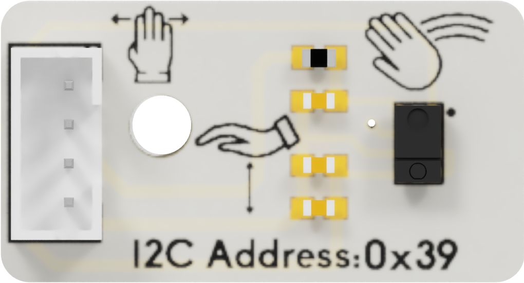 micro:bit v1, v2
APDS9960 sensor used in the Gesture module provides extensive capabilities for a tiny device. Please refer to Gesture Module for a detailed description of functionalities.
The Color and ALS detection feature provides red, green, blue light intensity data.
Results are returned as a number derived from RGB values.
This value can be used in various MicroBlocks blocks that have a color number parameter input, which looks like:

You can drag the block on top of the green circle, and set the color for the specific block.
NOTE:
APDS9960 color sensor results are very much influenced by the ambient light levels in your environment. As such, the performance and the results you obtain will vary widely from time to time, as lighting conditions change.
Also, the actual MicroBlocks sensor Library, Light & Gesture (APDS9960), has blocks to control the sensor sensitivity settings. If you are comfortable with the operational details of the sensor, you may find it useful to adjust some of the gain settings to achieve results closer to your expectations.
¶ Sample Code
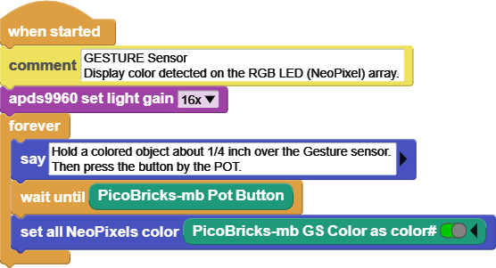
This sample loop waits for a button press and then detects the color of the object placed above the Gesture sensor. It then sets the RGB array (NeoPixel) colors to the detected color. Due to lighting conditions, the color detection will not always be accurate. Experiment with settings !
¶ PicoBricks-mb GS Detected


 micro:bit v1, v2
One of the functionalities provided by the APDS9960 sensor is gesture detection. Gesture detection utilizes four directional photodiodes to
sense reflected IR energy (sourced by the integrated LED)
to convert physical motion information (i.e. velocity, direction and distance) to a digital information.
This block returns a true / false value, depending on the detected motion over the sensor. In case of a true result, one can use the Last Gesture block below to obtain the actual gesture definition.
¶ Sample Code
Gesture sensor is used to detect hand movements in four directions above the sensor. Once a gesture is detected with the GS Detected block, its description is obtained via the Last Gesture block.
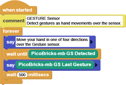
¶ PicoBricks-mb GS Last Gesture


 micro:bit v1, v2
This block works in conjunction with the block above, and helps one detect and interpret gestures over the sensor.
Returned results are self-explanatory: None, Up, Down, Left, Right.
¶ Sample Code
See above example for description.

¶ PicoBricks-mb GS Light


 micro:bit v1, v2
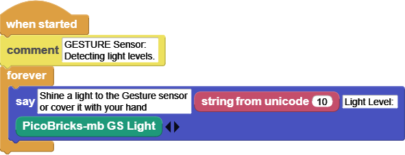
Returns the light level detected by the sensor. As with the color values, this value is also dependent on the ambient conditions and gain levels set.
To make meaningful use of this sensor reading, do not write code that relies on specific values; but rather use ranges to act on.
¶ Sample Code
Similar to the LDR, the Gesture sensor also has the ability to detect ambient light levels. A loop displays the light levels read, as one changes the setting.
¶ PicoBricks-mb GS Proximity


 micro:bit v1, v2
The Proximity detection feature provides distance sensing (eg: mobile device screen to user’s ear) by photodiode detection of reflected IR energy (sourced by the integrated LED).
However, this value is not directly a measure of the actual distance, but rather an indication of how near or far an object is from the sensor.
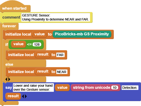
The values returned are 255 for the closest distance to the sensor and less and less as the object moves away. The interpretation and use of this data is up to the user and the project requirements.
¶ Sample Code
Proximity values represent how far an object is from the sensor. The values are interpreted to arrive at NEAR and FAR determinations. One can further enhance the script to take action depending on the results.
¶ PicoBricks-mb light sensor


 micro:bit v1, v2
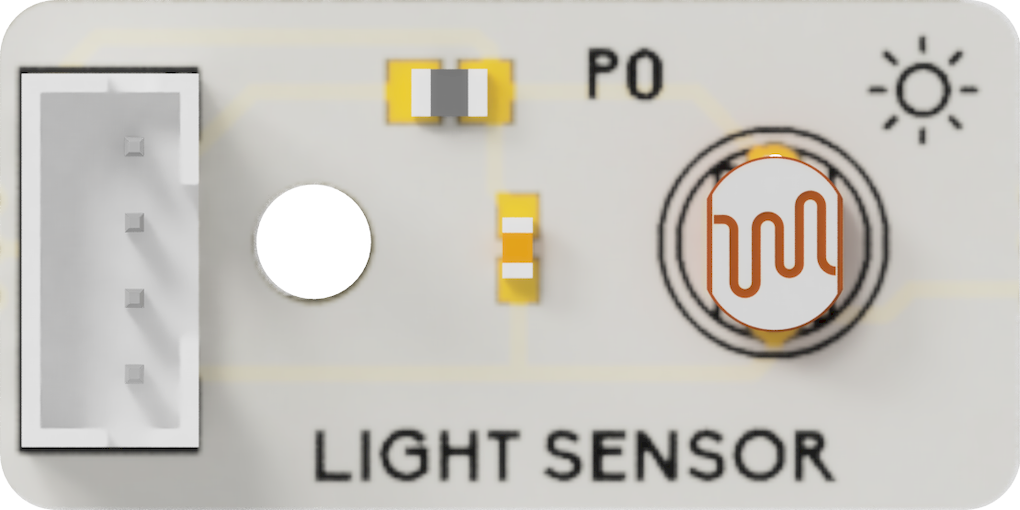
An LDR is a component that has a (variable) resistance that changes with the light intensity that falls upon it. This allows them to be used in light sensing circuits. Light Dependent Resistors (LDR) are also called photoresistors.
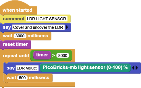
The values returned by this sensor are percentages proportional to the light detected. When there is almost no light, the values will be towards the low end (0). And when there is any light, depending on the type and intensity, the readings will be towards the high end (100).
¶ Sample Code
LDR sensor readings are displayed in a loop. Experiment as you change the setting.
¶ PicoBricks-mb Potentiometer


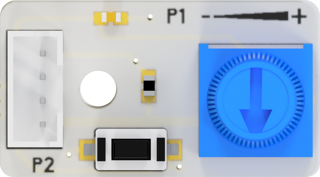 micro:bit v1, v2
A potentiometer is an ordinary variable resistor. It functions as a potential divider, which is used to generate a voltage signal depending on the location of the potentiometer. This is the signal that can be used for a very wide variety of applications including an amplifier gain control, measurement of the distance or angles, tuning of the circuits and many more.
Potentiometers are wired as variable voltage dividers: connect +V to one side, connect the other side to ground, and the middle pin will output a voltage between 0 and +V.
In our case, the the block will return values from 0 to 1023, representing the voltage range of 0 - 3.3V.
¶ Sample Code
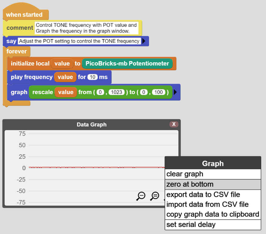
This example requires a minor setup for the graphing function:
- Drag the graph icon from the menu line onto to the IDE and enlarge it as seen in the picture.
- Then Right-click on it to open the options menu.
- Select "zero at bottom" to change the y-axis setting.
Now we are ready. As you run the script, pot values will be graphed, while at the same time, the tone frequency being played will be adjusted to the pot setting. We use a rescale block to convert pot values in the 0-1023 range to the graph limits of 0-100, only to make the graphing fit a small window. Otherwise, you can plot the values raw. Experiment both ways.
¶ PicoBricks-mb Pot Button


 micro:bit v1, v2
This block returns the status of the button next to the Potentiometer. The button is controlled via pin #2.
When the button is pressed, it will return a true value; when not pressed, it will return a false value.
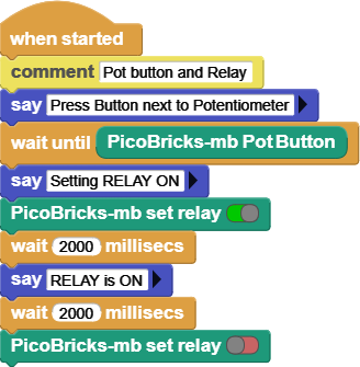
¶ Sample Code
This example prompts you to press the Pot Button, and waits for it.
When the button press is detected, the RELAY is switched on for two seconds. Then it is switched off.
¶ PicoBricks-mb Touchkey pressed


 micro:bit v1, v2
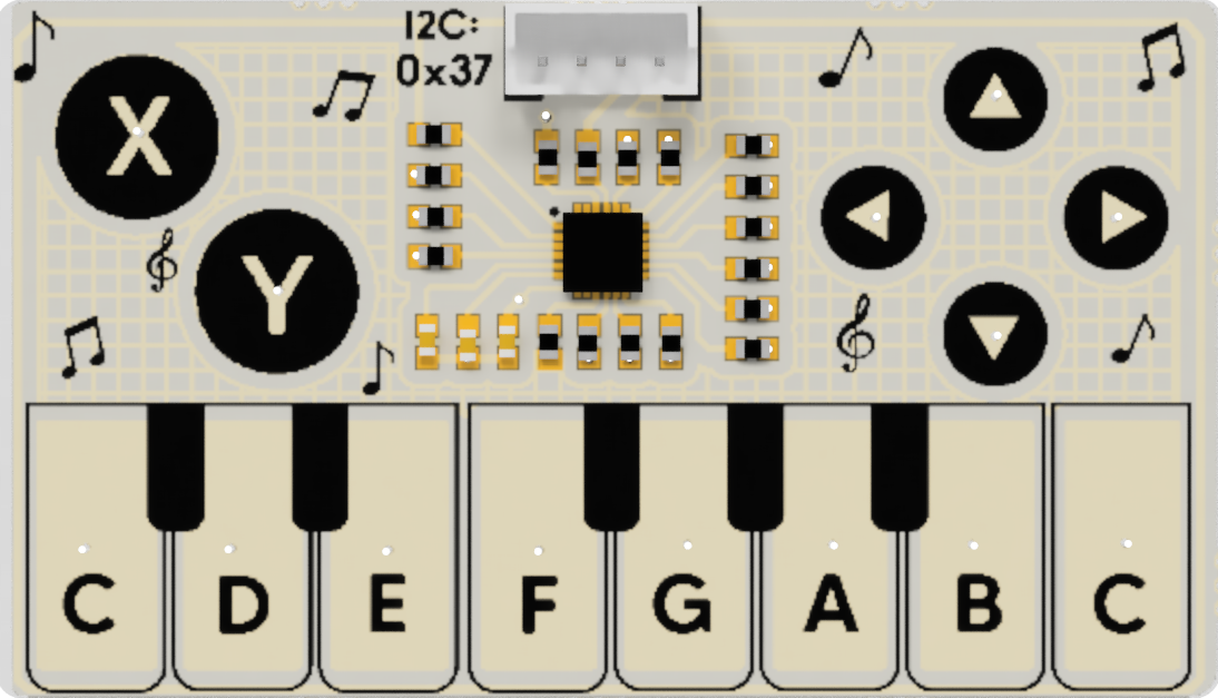
Touch Sensor controllers enable advanced, yet easy-to-implement, capacitive touch sensing user interface solutions, which supports up to 16 capacitive sensing inputs. Please refer to Touch Module for a detailed description of functionalities.
A capacitive sensor detects changes in capacitance to determine the presence of a touch or proximity to conductive objects. The capacitive sensor can be a capacitive button that replaces the traditional mechanical buttons, a capacitive slider that replaces mechanical knobs, or a proximity sensor that replaces an infrared sensor in a user interface solution.
The capacitive user interface system serves as a human-machine interface that takes the user’s touch inputs and provides audio-visual feedback through a buzzer or an LED.
This block returns a true / false response depending on the touch detection on the touch module. Various selection options lets the user focus in on specific keys or just an overall touch of any key.
In case of a true result, one can obtain the Last key touched with the help of the next block.
¶ Sample Code
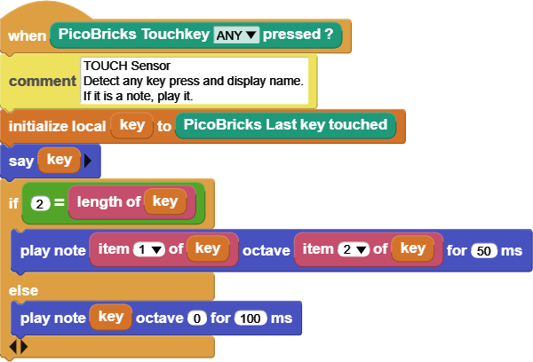
This block returns true / false, based on what key selection has been made in the menu. when a touch is detected, the description of the touch key can be retrieved with the help of the Last key touched block, below.
¶ PicoBricks-mb Last key touched


 micro:bit v1, v2
As the name implies, returns the last key touch detected. The result names are the same as can be found in the previous Touchkey pressed selection menu.
Note that this block in itself does not detect a touch. That operation has to be done using the previous block. It only reports on the result of the last touch event.
Please refer to Touch Module for a detailed description of functionalities.
¶ Sample Code
See sample description above.

¶ _PicoBricks-mb configure Touch Options


 micro:bit v1, v2
Touch sensor used on the PicoBricks micro:bit board has the ability to adjust its firmware to enable and disable sections of the touch module. If you look at the touch pad, you'll notice that there are several sections with buttons of similar functionalities: X & Y buttons, Arrows, and the Keyboard.
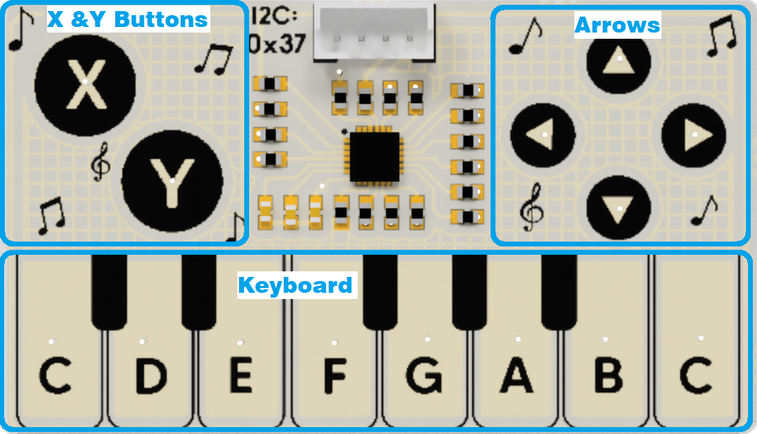
This block gives the user the ability to hone in on the specific functionality they desire, while blocking out the rest of the touch module. Here are the various selections one can make:
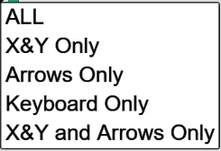
After selecting one, firmware will be reconfigured and the module will be restarted to implement the changes. Depending on the selection made, the touch sensing of the module will be changed to the section selected.
Please refer to Touch Module for a detailed description of functionalities.
Note:
Make sure that you do NOT have any Touch sensor blocks running before attempting a configuration change.
Simplest way to do that is to click on the STOP icon on the IDE.
Modifying firmware of the touch module will not affect your scripts in the IDE or on the microcontroller.
¶ _PicoBricks-mb show Touch Config&CRC


 micro:bit v1, v2
In order to ease the fact of keeping track of any firmware changes and to query the current operational settings, this block displays the configuration and the CRC of the current configuration. Configuration will be one of the menu selections made in the previous block. CRC is displayed in decimal and hex notation.
Please refer to Touch Module for a detailed description of functionalities.
¶ Sample Code

¶ _PicoBricks-mb init Library
 micro:bit v1, v2
PicoBricks-mb board components are pre-assembled and wired via the printed circuit board they are mounted on. Therefore their connections to the micro:bit processor is predetermined by the manufacturer of the board. As long as you do not break off the components and reassemble them to your liking, the pins assignments to drive them are as specified in this block.
In addition to pin assignments, this block also sets I2C addresses of several modules, and preconfigures settings for some related libraries (NeoPixel, Tone, IR Remote).
If you break off / separate the components and rewire them to other pin locations, you can change the assignments in this block and continue using the library.
NOTE:
Initialization of the PicoBricks-mb library, for all practical purposes, is automatically done by any of the blocks used. The only exception is the touch configuration change block, since that function is not dependent on the library itself.
¶ Notes on Library Components
PicoBricks-mb board contains thirteen components pre-mounted. The Library, however, only has blocks for ten of them; the OLED screen, NeoPixel (RGB), and WIFI Comm components are not directly covered by this library.
In this section, we will describe how one can make use of these components, as well as some detailed information about Motor Controller, Gesture, and Touch sensors.
¶ OLED Display

 micro:bit v2
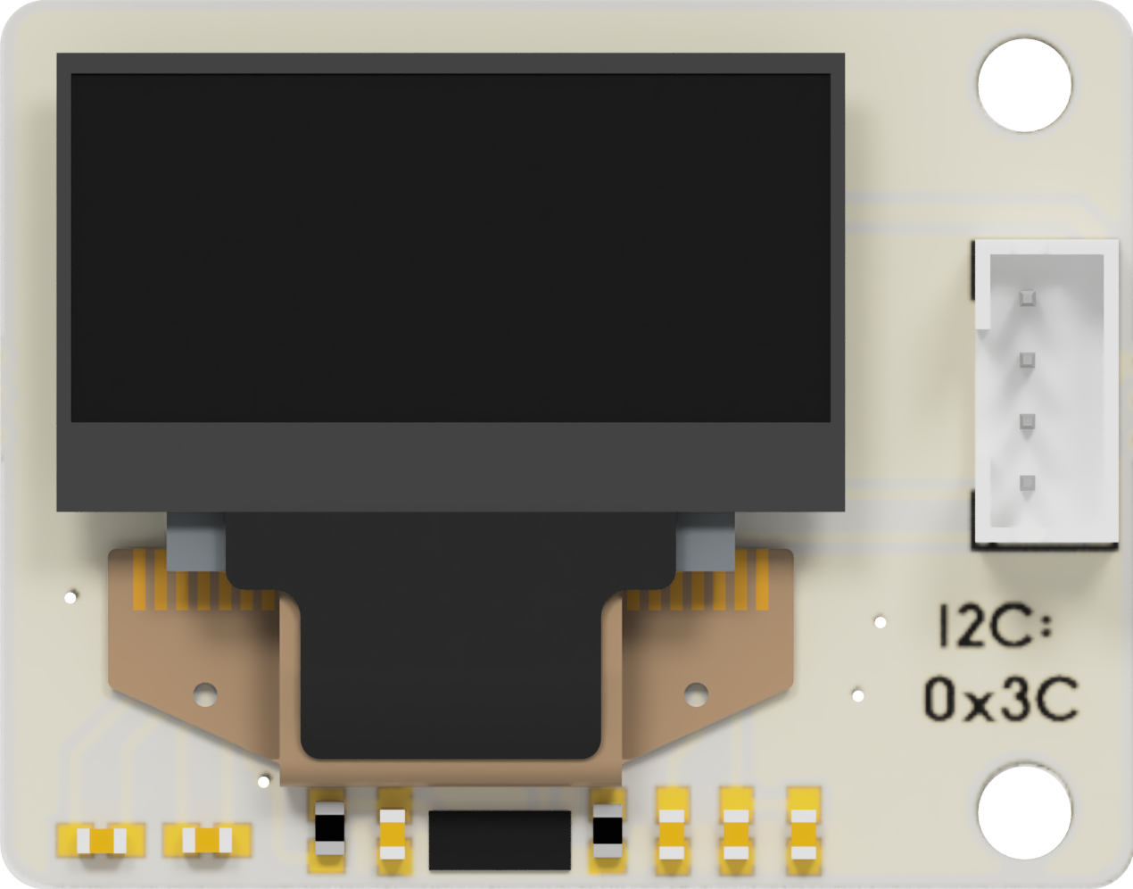
There are two ways to program the OLED display module:
- by using the MicroBlocks graphics library called OLED Graphics. It is located under Libraries+ / Graphics / OLED Graphics in the IDE.
- by using the MicroBlocks graphics library called TFTs. It is located under Libraries+ / Graphics / TFT in the IDE.
For details of the OLED library blocks and operations, refer to OLED Library. OLED and TFT blocks are very similar in functionality. Familiarity with one will assist in understanding the other.
For a project that describes advanced use of the library and data transfer, please refer to SNAP to MicroBlocks.
NOTE:
The main differences between the two libraries are as follows:
- OLED library size is 26K, TFT size is 3K
- OLED cannot adjust text sizes, TFT can
- OLED only works with monochrome SD1306 and SD1309 displays, TFT blocks will function with displays that support color
- OLED supports 5x5 sprite use, TFT does not
- OLED supports fully buffered graphics and text composition, TFT does not
- OLED supports columnar text composition, TFT does not
- OLED supports inverse text and graphics, TFT does not.
¶ NeoPixel (RGB)

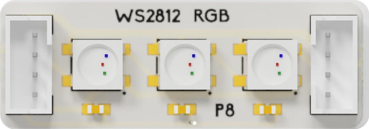 micro:bit v1, v2
The NeoPixel module of the PicoBricks-mb kit has three RGB LED units. Since MicroBlocks already has a NeoPixel library, we direct the user to work with it directly, rather than provide wrapper functions in this library.
The PicoBricks-mb library initialization automatically initializes the NeoPixel controls as needed. And since the NeoPixel library is declared as a dependency to the PicoBricks-mb library, it will be automatically loaded whenever PicoBricks-mb is loaded.
Remember that PicoBricks-mb Gesture sensor color blocks can be integrated with the NeoPixel blocks' color inputs.
¶ WIFI Comm Module

 micro:bit v2
This module enables PicoBricks to communicate with other environments using the WIFI capabilities of the ESP01 (ESP8266).
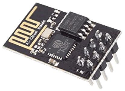
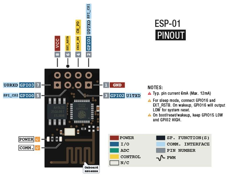
If you decide to use this module, please make sure to insert it in the correct orientation into its socket. The unit should be inserted such that the antenna part extends over the IR receiver or is towards the right edge of the board.
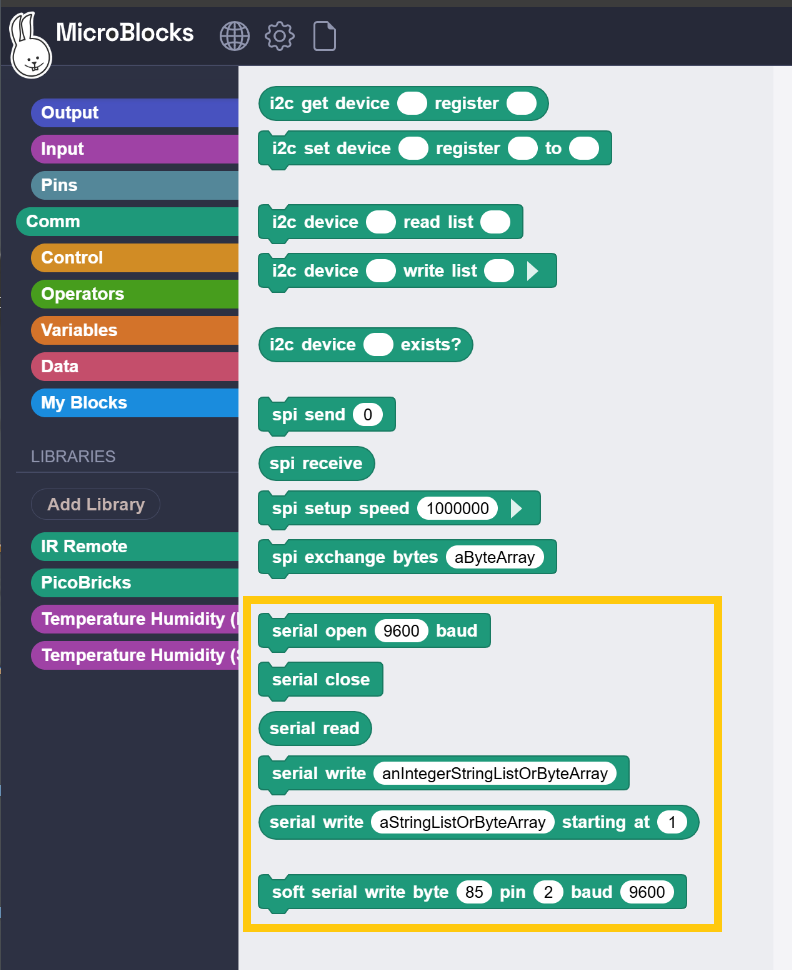
WIFI Comm module is programmed using the AT command set of the ESP01 board. Since the AT programming is done over the Serial comm port of the processor, the command blocks to do that are already present in the MicroBlocks.
 |
 |
|---|
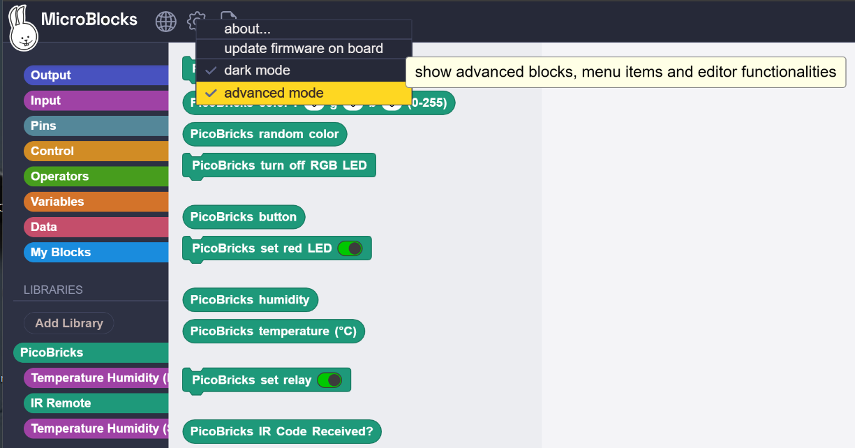
Simply enable the advanced mode option under the MicroBlocks (Gear) in the menu. This will display the Comm blocks category. Within you will find the Serial set of blocks.
NOTE:
Programming of the ESP01 WIFI module using the AT command codes is outside the scope of this documentation. One can refer to the Espressive ESP-AT User Guide for further details.
¶ Motor Control Module


First thing we should note about this module (mb version) is its differences from the module included in the previous version of the PicoBricks Board for Raspberry Pi RP2040 (pi version):
pi version:
- drives 2 DC motors and 2 Servos
- DC motor do not have directional control; only way to change direction is to reverse wires.
- DC / Servo selection is done via jumpers
- interface operates via digital pin controls
mb version:
- drives 2 DC motors and 4 Servos
- DC motors have directional control implemented via respective bloks
- DC / Servo selections are done in software via respective blocks
- interface is via the HK32F030 chip that operates over the I2C bus.
- Full power is supplied via an on-board battery connection. Without this battery, only a very limited number of motor/servo can be used, and at limited performance levels.
If you are a user familiar with the pi version of the boards, you may have written scripts to drive the motors / servos. Those scripts will not function with the mb version, and need to rewritten using the new library blocks. Refer to block descriptions above.
Due to the power limitations of the micro:bit microcontroller, full use of the motor controller is ony possible when a battery is attached to the board battery connector.
If you do not use that supplemental battery, then only a limited amount of DC motors and Servos can be programmed. You will experience very slow operational speeds, and potential brownouts due to excessive power drawn.
It is strongly suggested that the on-board battery be used with motor controller.
¶ Gesture Module


The APDS-9960 device features advanced Gesture detection, Proximity detection, Digital Ambient Light Sense (ALS) and Color Sense (RGBC).
Let's try to define what these features mean:
-
Gesture detection - is the ability to detect movement above the sensor in any one of the four directions. Gesture detection utilizes four directional photodiodes to sense reflected IR energy to convert physical motion information (i.e. velocity, direction and distance) to digital information.
-
Proximity detection - is the ability to gauge the vertical distance from the sensor surface. Note that the distance mentioned is not a discrete value in any distance measurement unit (cm, inches, etc) but rather a relative number from 0 - 255. Lower numbers are indicative of far away objects and higher numbers are indicative of nearer objects. The interpretation and application of this information is totally up to the user.
-
Digital Ambient Light (ALS) and Color Sense - The Color and ALS detection feature provides red, green, blue and clear light intensity data. Each of the R, G, B, C channels have a UV and IR blocking filter and a dedicated data converter producing 16-bit data simultaneously. Using this information, the sensor can be programmed to recognize colors of the objects nearby, as well as environmental light levels. Low ALS levels indicate darkness, and high levels indicate brightness. Color detection is very much dependent on the lighting levels and will vary from time to time.
It should be noted that MicroBlocks Libraries already have a gesture sensor library "Light and Gesture APDS9960". In PicoBricks micro:bit library, we make use of this library by providing wrapper functions for the most used features. This serves two purposes:
It helps PicoBricks users to access the MicroBlocks library without actually learning about it. And yet they can still switch to the actual library blocks and get access to advanced features.
The original library code is dependent on the first version of the sensor use we had encountered in a product. In that version, the mounting of the sensor was different than what is used in PicoBricks micro:bit. Therefore, the gesture orientations were rotated 90 degrees when compared to the PicoBricks version. The blocks in the PicoBricks library account for this difference and provide corrected gesture results.
For users who would like to experiment with this sensor by accessing the original library blocks, it important to remember this difference.
¶ Touch Module


The CY8CMBR3xxx CapSense® Express™ controller enables advanced, yet easy-to-implement, capacitive touch sensing user interface solutions. This sensor family supports up to 16 capacitive sensing inputs and is ideal for implementing capacitive buttons, sliders, and proximity sensing solutions.
In the PicoBricks implementation, 14 sensors are used in three groups: X & Y Buttons, Four directional arrows, and an eight-key keyboard.
The library blocks provide configuration support for ALL or several combinations of these sensor groups, depending on the needs of the user projects.
PicoBricks micro:bit kit provides a variety of use and programming options, eg with MicroBlocks, with MakeCode, with Arduino, as well as coding in text-based languages like Python, C++, and Javascript/Typescript. All these environments have different ways they handle the configuration of the PicoBricks hardware. Not knowing which way the user has started makes it hard to determine the operational status of the sensors. Therefore, we suggest that you start your exploration in MicroBlocks by using the Touch block PicoBricks-mb show Touch Config&CRC. This block will display the configuration status of the touch sensor.
If you get a display that says "unrecognized config", it may indicate that your touch sensor has not been configured yet, or configured in a way not recognized by MicroBlocks. If that is the case, you can then make a config change selecting the ALL option in the PicoBricks-mb configure Touch Options block. This will get you started in the simplest way.
Once you are comfortable with how things work, then you can experiment with different options.
In the PicoBricks Demo program, when the keyboard keys are touched, corresponding musical notes are emitted from the micro:bit v2 speaker. The user should be aware of several things with this behavior:
- the sensor itself is not capable of producing any sounds; it only detects key touch events.
- the sound is produced with the help of MicroBlocks Tone library
- Since the PicoBricks micro:bit kit does not contain any speaker components, the sound is emitted from the speaker on micro:bit v2. If you use a micro:bit v1, there will be no sound. This is one of the reasons why micro:bit v2 is the better choice for this board.
- The final result of touching keys playing notes is the result of coding in the Demo program. Looking at this code will provide an excellent learning opportunity for combining touch sensor event detection with different ways of reacting to them.
Enjoy your kit.