¶ MICROBIT
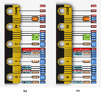
Pins 0-20: pads and edge connector (except 17 & 18, which are 3.3v connections)
Button A: pin 5
Button B: pin 11
Pins 23-28: COL4, COL5, COL6, ROW1, ROW2, ROW3
Analog input:
	pins 0-4 and 10
Serial: RX-pin 0, TX-pin 1
I2C:
	Pin 19 - SCL
	Pin 20 - SDA
SPI:
	Pin 13 - SPI Clock
	Pin 14 - SPI MISO
	Pin 15 - SPI MOSI
¶ MICROBIT V2
Pins 0-20: pads and edge connector (except 17 & 18, which are 3.3v connections)
Button A: pin 5
Button B: pin 11
Speaker: pin 27
Analog input:
	pins 0-4 and 10
	Microphone: pin A6
Serial: RX-pin 0, TX-pin 1
I2C:
	Pin 19 - SCL
	Pin 20 - SDA
SPI:
	Pin 13 - SPI Clock
	Pin 14 - SPI MISO
	Pin 15 - SPI MOSI
¶ CALLIOPE MINI
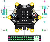
Pins 0-19 are for the large pads and 26 pin connector
Button A: pin 20
Button B: pin 22
Motor/Speaker: pins 23-25
NeoPixel: pin 26
Analog inputs:
	A0 - microphone
	A1, A2 - pads 1 and 2
	A3, A4, A5 - connector pins 4, 5, and 6
	A6, A7 - connector pins 17, 18 and Grove connector 2
Serial: not supported
¶ CIRCUIT PLAYGROUND EXPRESS
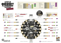
Pins 0-7 Pads on board
Pin 8 - button A
Pin 9 - button B
Pin 10 - slide switch
Pin 11 - IR receiver
Pin 12 - IR transmitter
Pin 13 - red LED
Pin 14 - neopixels
Pin 15 - speaker disable
Analog inputs:
	A0-A7 - Pads on board
Serial: RX-pin 6, TX-pin 7
¶ CIRCUIT PLAYGROUND BLUEFRUIT
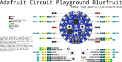
Pins 0-7 Pads on board
Pin 8 - button A
Pin 9 - button B
Pin 10 - slide switch
Pin 11 - neopixels
Pin 12 - red LED
Analog inputs:
	A0-A7 - Pads on board
Serial: RX-pin 6, TX-pin 7
¶ CLUE
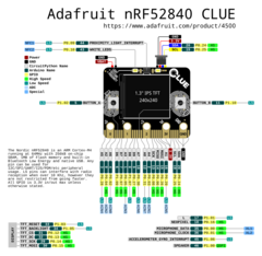
Pins 0-20 Edge connector pins (except 17 & 18)
Pin 17 - red LED
Pin 18 - NeoPixel
Pin 21 - speaker
Pin 22 - white LED
Serial: RX-pin 0, TX-pin 1
I2C:
	Pin 19 - SCL
	Pin 20 - SDA

Clue i2c sensor addresses:
	28 - LIS3MDL magnetometer
	57 - APDS9960 light & gesture
	68 - SHT31-D temp & humidity
 106 - LSM6DS accelerometer & gyroscope
 119 - BMP280 temperature & air pressure
¶ RPi PICO
https://datasheets.raspberrypi.com/pico/pico-datasheet.pdf
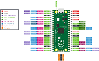
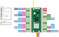
External Pins
	Pins 0-22 - digital only
	Pins 26-28 - analog or digital
	Serial
	Pin 0 - TX
  Pin 1 - RX
	I2C
		Pin 4 - SDA
		Pin 5 - SCL
	SPI
		Pin 16 - SPI MISO
		Pin 17 - SPI SS
		Pin 18 - SPI Clock
		Pin 19 - SPI MOSI

Internal Pins
	Pin 23 - (digital output) turn on for better voltage regulation (uses a bit more power)
	Pin 24 - (digital input) detects USB connected
	Pin 25 - (digital output) user LED
	Pin 29 - (analog input) temperature sensor
¶ ESP32 boards including the M5Stack
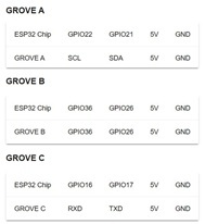
I2C: SDA-pin 21, SCL-pin 22
SPI: MOSI 23, MISO 19, CLK 18, CS 5
Serial: RX-pin 16, TX-pin 17
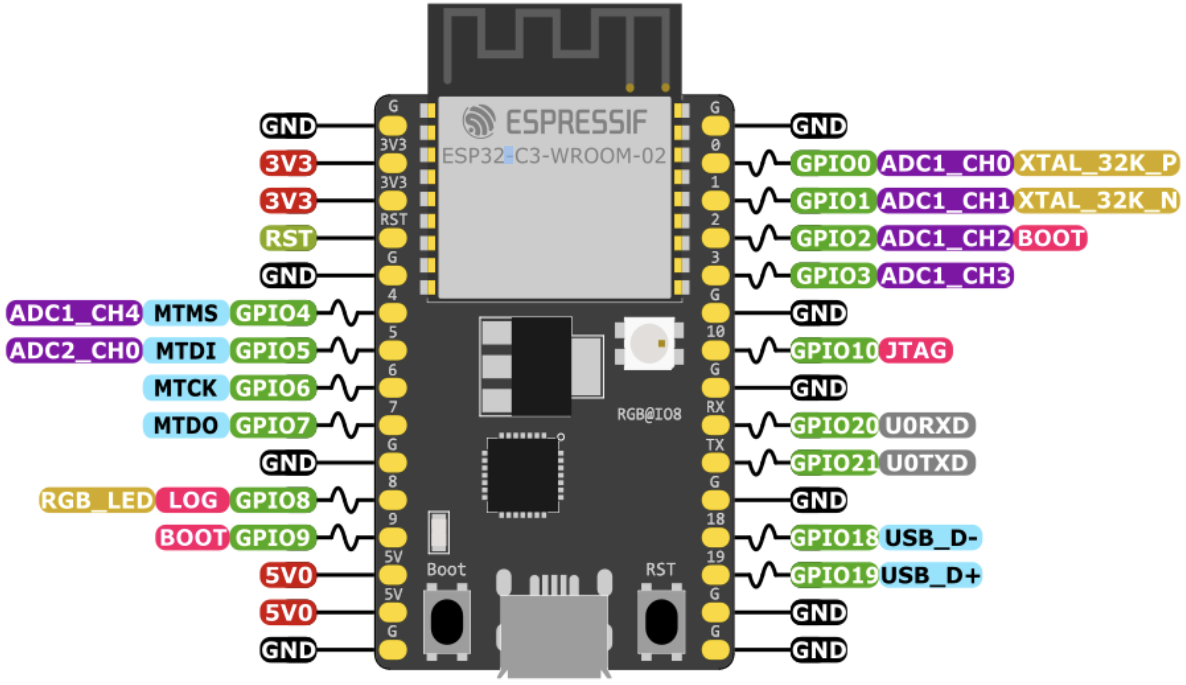
¶ ESP32-C3
13 usable pins: Pins 0-10 + 2 serial pins (which can also be used as GPIOs)
Pins 0-5 can be used for analog input

Serial:
	Pins 18-19 on boards with USB-serial converter
	Pins 20-21 on boards that use built-in USB-serial
I2C: SDA-pin 8, SCL-pin 9
Default NeoPixel: pin 8 (DevKitC-02)
Note: Boards that use built-in USB-serial may require manually entering boot mode before installing firmware by holding boot button for two seconds or holding the boot button while toggline the reset button. See the documentation for your board.
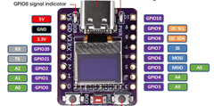
¶ ESP32-C3 SuperMini
13 usable pins: Pins 0-10 + 2 serial pins (which can also be used as GPIOs)
Pins 0-5 can be used for analog input

Serial: RCV-pin 20, TX-pin 21
I2C: SDA-pin 8, SCL-pin 9
LED: pin 8 (active low)
Note: Boards that use built-in USB-serial may require manually entering boot mode before installing firmware by holding boot button for two seconds or holding the boot button while toggline the reset button. See the documentation for your board.
¶ ESP32-C3 with 0.42in OLED (72x40)
NOTE:
This board is NOT officially supported by MicroBlocks. However, it is functional when used with the vm_esp32-c3-mini.bin VM from the VM Downloads page of the Website.
I2C use requires a pin REASSIGNMENT to SDA-pin 5, SCL-pin 6 using theblock of the Sensor Primitives library.
OLED Graphics Library supports this display after the pin reassignment mentioned above.
13 usable pins: Pins 0-10 + 2 serial pins (which can also be used as GPIOs)
Pins 0-5 can be used for analog input

Serial: RCV-pin 20, TX-pin 21
I2C: SDA-pin 5, SCL-pin 6
LED: pin 8 (active low)
SAFE PINS: 00 01 03 08 09 10
AVOID: 02 04 05 06 07 20 21
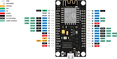
¶ ESP8266
Serial: TX-pin 4 (no RX; supports serial transmit only)
¶ Adafruit ItsyBitsy MO
23 general purpose pins

A0 - DAC analog output
D13 - User LED
D26 - DotStar Data
D27 - DotStar Clock
Serial: RX-pin 0, TX-pin 1
SnoPixel Neopixels - pin 7
¶ Adafruit Trinket MO
5 general purpose pins + 2 dotstar pins (7 total)

A0/D1 - DAC analog output
D5 - DotStar Data
D6 - DotStar Clock
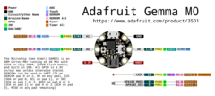
¶ Adafruit Gemma MO
3 general purpose pins + 2 dotstar pins (5 total)

A0/D1 - DAC analog output
D3 - DotStar Data
D4 - DotStar Clock
