¶ Overview
WiFi Remote Control with WebSocket tutorial in the WIFI Remote Control category, describes the use of the WebSocket protocol between a MicroBlocks programmed microcontroller and an APP Inventor APP. It focuses on getting familiar with the Websocket Library and associated programming to make the two sides communicate.
This tutorial is about implementing a a GAMEPad interface using the same protocol, that can be used to drive robotic vehicles, play games, or anything else you can program. And it will expose more of the programming details on MicroBlocks and APP Inventor sides.
Since the APP uses a popular 8-button generic GamePad interface, we'll program the mobile APP to send commands representing the 8 buttons. There are slight variations of this interface with more buttons, colors, and joystick etc. But the programming concepts will be the same and applicable to the other models as well. One only has to redo visual interface to match their favorite controller.
Microcontrollers that can be used in this project should have several common features:
- they should support WIFI
- they should have a button (optional) to be able to switch between Network Client and AP operation modes.
In the picture below, we show ESP-WROOM-32 microcontroller with BOOT and EN buttons. You may have other suitable choices available to you.
We supply the MicroBlocks demo program and the companion mobile APP for Android phones, so you can use it as a remote control device.
Let's start examining the details.
¶ Parts
To complete this tutorial you will need:
- a WIFI capable microcontroller: we use ESP32
- an Android Phone
These are the basic requirements. Since the controller can be used for various purposes, we have refrained from programming it for a specific purpose, like driving a robotic car.
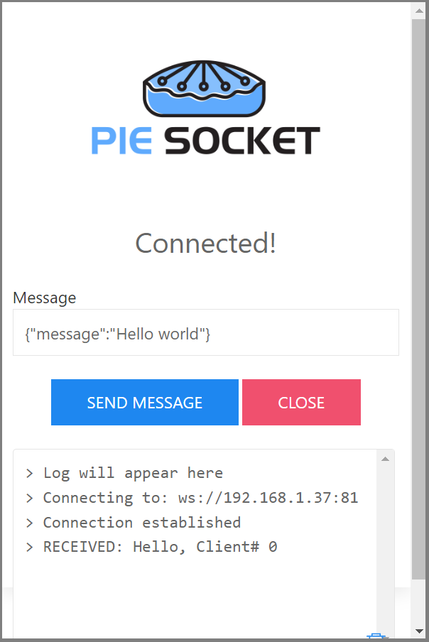
- If you do not have access to an Android phone, then you can install the PieSocket WebSocket Tester extension for Chrome and work with that. This will enable you to test the command exchange. But for final use, you will need an Android phone.
¶ Making the connections
Since this exercise makes use of the WIFI capability of the devices in use, there will be no need for physical cabling. However, your project might use a sophisticated robotic device or such, and it will be up to you to make that part happen. We assume an ESP32 is available and operationally integrated to whatever system you intend to control.
As far as the WIFI availability goes, you can start by using the WIFI provided by your local Internet router.
Alternatively, you can also create your own WIFI AP using the the ESP32 and provide your own WIFI signal. This will be handy if you plan on operating in an area without a WIFI service present.
¶ Scripts
MicroBlocks project is coded in the program GAMEPadWIFIRemote.ubp.
ESP32 microcontroller, acting as a WebSocket server, is programmed to:
- Act as a WIFI client on the local wireless network or become a HOTSpot providing a WIFI AP service
- send, receive, and display messages
- turn on and off the User LED on the microcontroller
- place each socket into loopback mode
- support up to five clients, all operational
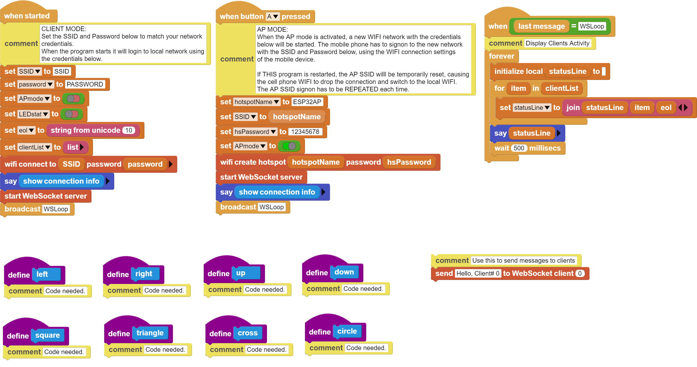
In the project scripts picture below,
-
when started block signs on to the local WIFI network, starts the WebSocket server, and will display the connection information. It will then start the WSLoop process to start handling the network activity.
-
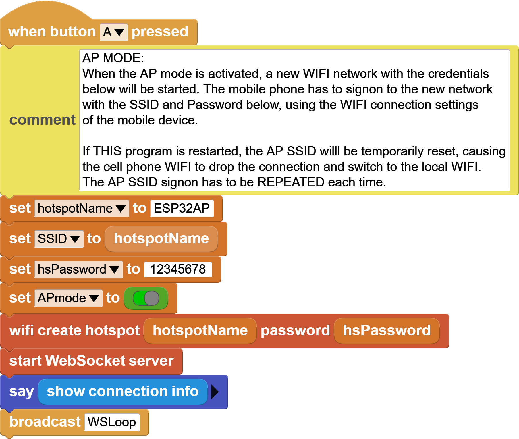
when button A pressed handles the setup for HOTSpot or AP mode. Displays the connection information and starts WSLoop to process Websocket messages.
-
when lastmessage = WSLoop constantly displays all the messages that arrive over the WebSocket connection.
-
Definitions of 8 button actions (left, right, up, down, square, triangle, cross, circle) are placeholders for the actions to be programmed for these buttons. You need to pprogram these according to the applicaton design. The incoming commands will always be the same, but what they do can change depending on your code.

When you are testing your project, you can use the WebSocket send block to send a message to a client on a specific socket number. In order to do that, you need to make a note of the displayed Client ID at the phone APP when a connection is made. Then direct your message to that specific client number using this block. On the Android APP, client ID will be displayed in the messages area of the display.

¶ Custom Scripts
There are other scripts in the My Blocks section of the IDE that are used to perform the lower level details of the messages and necessary display actions.

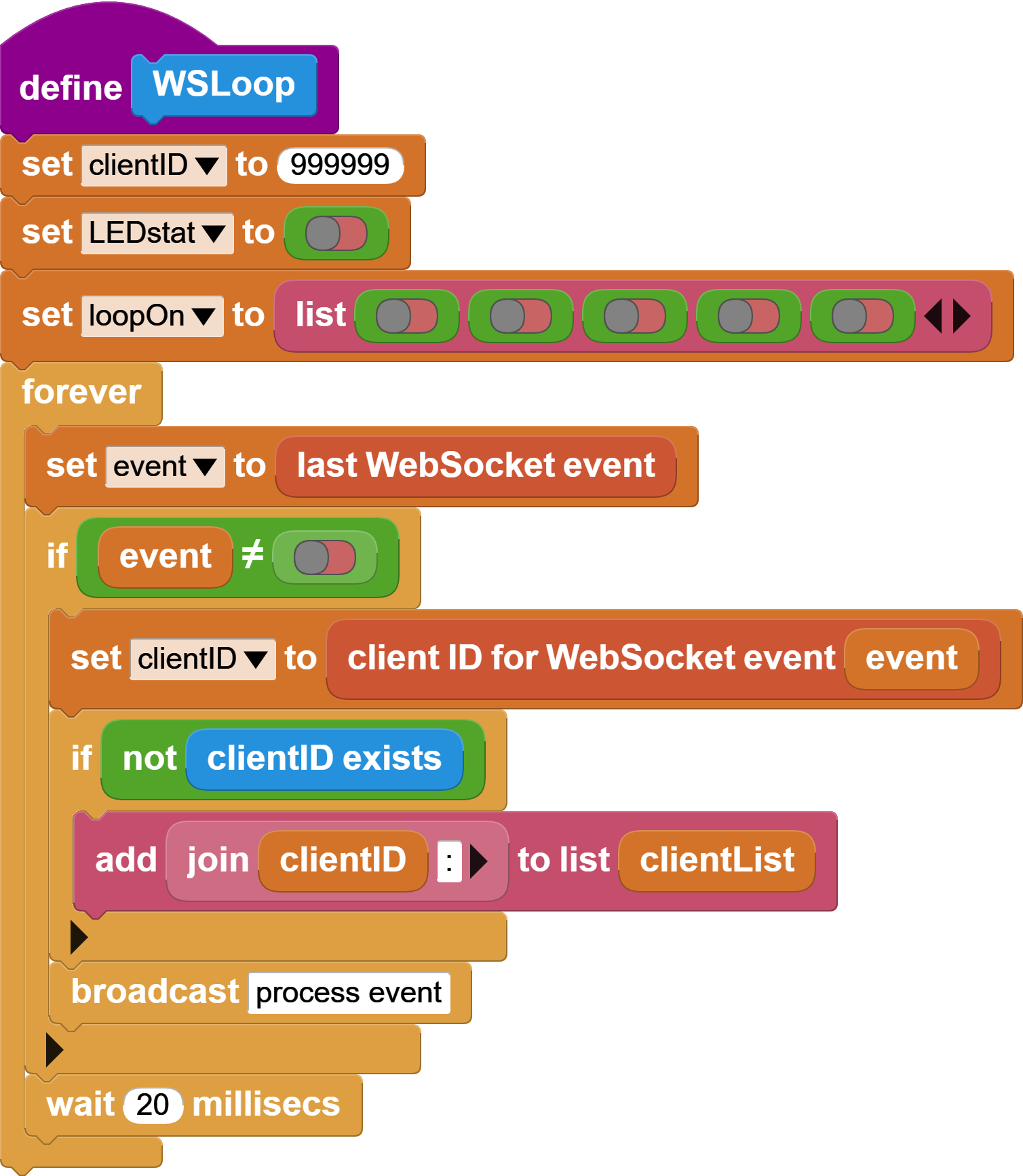
sets up the project variables and then the script enters a loop of receiving messages and dispatching them to the process event logic to be handled. Incoming mesages are checked for new client connections, If found, it will add it to the clientList variable to keep track of it.

script deciphers the WebSocket connect, disconnect, and text message payload types. Text message payloads are dispatched to processText script to be handled.

script handles all the main messages of the program (LED, LOOP, left, right, up, down, square, triangle, cross, circle). Depending on the payload received, different scripts are executed to proces the incoming messages.

This project supports up to five remote clients connecting to the WebSocket server. This script verifies each received message to check if the client already exists. It will return true or false depending on the status of the client.

This script is used to toggle the on-board LED on and off. It can be used to provide a simple confirmation that the connection is operational.

Each socket of the WebSocket server is independently controlled and looped back when the Loopback command is received. This enables the user at the Android phone end to send messages to the server and have the server send them back. This feature can be used to verify that an end-to-end socket connection is operational.

When the server signs on to the local WIFI network, it obtains an IP address. This script returns the SSID and the obtained IP address. If the connection type is AP,, then the new network credentials are displayed.


¶ Process
This project requires an Android APP running on an Android phone or similar device, and the MicroBlocks GAMEPadWIFIRemote program running on the ESP32 microcontroller. ESP32 is acting as the Server and the Android device is the Client.
¶ Establishing a Connection
This project allows you to operate in two different modes of connectivity:
- Local WIFI access
- HotSpot or AP mode
¶ Local WIFI Mode
When the program starts, it will signon to the local WIFI network using the credentials provided in the when started script. Remember to replace the SSID and Password in the script with your specific WIFI credentials.
When the connection is established you will see the SSID and the IP address acquired displayed on the IDE. Make a note of these.
You can continue with the project in this state. Provided your mobile phone is also using the same local WIFI connectivity, everything will work OK. You can skip the next section if this is how you want to operate.
If you decide to work in this mode, you have to do the following to continue with the project:
- You need to make sure your mobile phone's WIFI is using the same network.
- Start your mobile APP
- Enter the IP address displayed on the MicroBlocks program into the top entry area. This should look like 192.168.1.48.

Depending on your local WIFI network configuration details, the IP address provided by your router may be of a different range than the one shown here.
What is important is that your phone IP and the IP assigned to your ESP32 are on the same subnetwork. That means they both have to have the same initial three numbers in the assigned IP addresses.
¶ HotSpot or AP Mode
For those working in an environment without a local WIFI connection, we have provided the option of setting up the ESP32 microcontroller in a HotSpot or AP mode, and generate a WIFI signal to facilitate WebSocket connections.
This mode is activated by pressing the BOOT button on the ESP32. BOOT button is recognized by MicroBlocks as button-A. As such, the program will execute the code under when button A pressed and switch to the AP Mode. It will reconfigure the ESP32 to setup a WIFI network with SSID of ESP32AP, and a password of 12345678.
When the new operational mode is active, you will see the SSID, IP Address, and Password displayed on the IDE. Make a note of these.
If you activate this mode, you have to do the following to continue with the project:
- You need to change your mobile phone's WIFI settings to signon to the new network.
- Initiate a WIFI scan in the WIFI settings area of your phone and then select the network SSID ESP32AP. Use the password 12345678 and signin.
- Start your mobile APP
- Enter the IP address displayed on the MicroBlocks program into the top entry area. This should look like 192.168.4.1.

You can now proceed to use the APP.
¶ WebSockets in our Project
Now, we will examine, in detail, all the scripts that are required in the WebSocket message handling of the MicroBlocks project. There are three main scripts involved:
¶ WSLoop
In the Local WIFI mode, your Socket address is: 192.168.1.48:81
In the HotSpot/AP mode, your Socket address is: 192.168.4.1:81
Your specific IP addresses may be different depending on your network configuration.
MicroBlocks implementation of the WebSocket port will be 81.
This is the main loop that reads the socket and handles the message dispatch. The presence of a Websocket event / message is indicated by the block lastWebsocketevent. If it is false, there is no message.
If there is a message, then this block returns an event object that is used to parse the various components of the message. Following blocks show blocks for components event type, client id, and payload.


Provided the event is not false (false, no message), the processing loop proceeds to save the clientID and checks for the presence of the clientID in the active clientList. MicroBlocks supports 5 client connections per socket. We keep track of the incoming connection requests and handle them separately by each client ID.
 block starts the Websocket event processing script to handle the specific events. Note the special use format of the broadcast block. Instead of a broadcast message name, we are using the name of a custom block we have defined. This has the effect of initiating the execution of an independent thread of the script called.
¶ process event
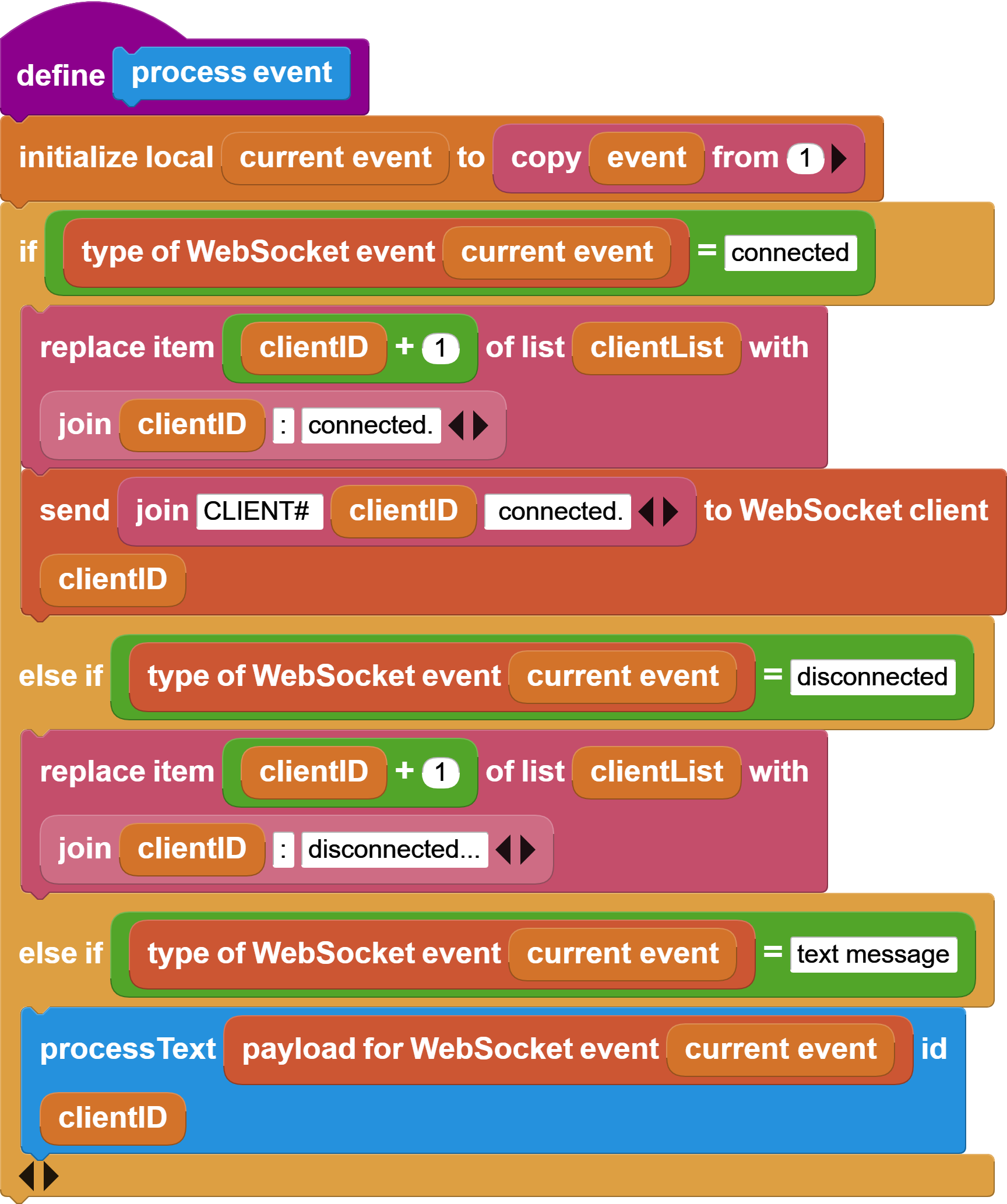
This script has the responsibility to parse three specific types of events: connected, disconnected, text message.
In the case of connected, we update the clientList to indicate the connection, and send a message to the client connection identifying the ID.
In the case of disconnected, we update the clientList to indicate the disconnection.
In the case of text message, we dispatch the payload and client ID to the script responsible for processing the programmed commands.
¶ process text
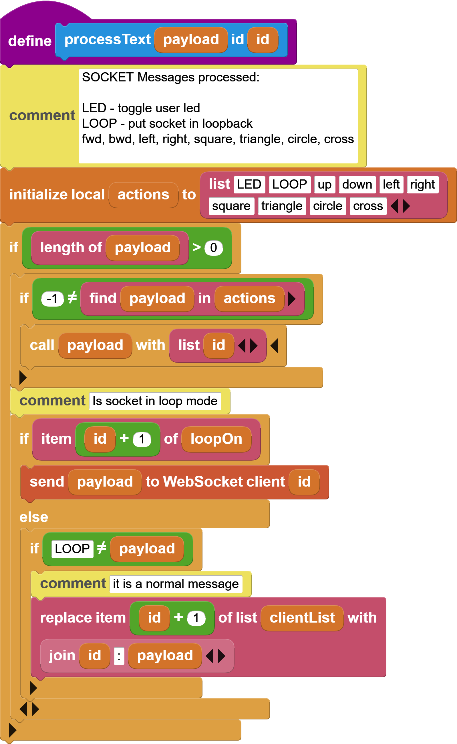
This script handles all the programmed commands we have designed into our project.
We use a actions list representing all the commands we will process:

Incoming payload parameter is searched in the actions list and if found, we call a custom block function we have programmed with the same name as the payload.
eg: if we receive a payload of circle, then we lookup circle in the actions list. Since it exists, the search result is not equal to -1 (-1, indicating not found). Then we call the custom block ![]() .
.
We have to handle a special LOOP command as a feature to help us debug connections. When a client connection sends the LOOP command, that connection is put into loopback mode and all subsequent messages arriving will be returned back to the client. This will allow the client side to verify that a connection exists and is active. While this is of little use whe the mobile APP and the controlled device is in the same room, it can be of great use whe they are located apart from each other, only connected by the Internet link.
If the payload is not LOOP, then we also update the clientList to show the command name we have received.
This concludes the explanations of the WebSocket related logic in MicroBlocks side of our project. Now we move on to the APP Inventor side of things.
¶ App Inventor APP
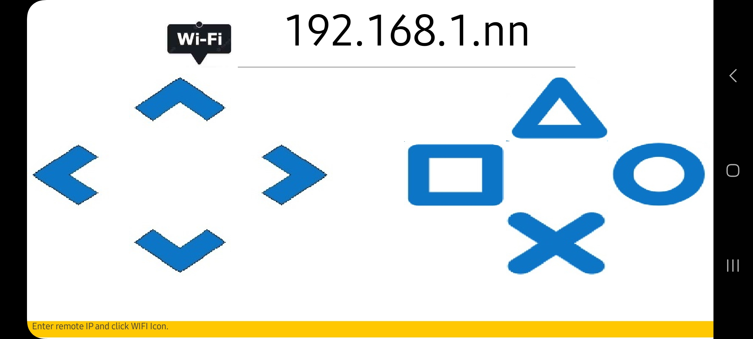
We have provided an Android companion APP for the MicroBlocks GAMEPadWIFIRemote program. It implements a very simple GAMEPad interface with 8 buttons, a message display area, and a WIFI IP Address entry field.
Below image displays the APP GUI at the start of the program:
¶ APP User Interface
The APP GUI consists of three parts:
- WIFI IP / Connect / Disconnect: used to enter the ESP32 IP address and connect and disconnect to/from it.
- GAMEPad Controls Area: 8 button controls implemented in two groups of four.
- Message Display Area: All exchanges of the program and any error messages are displayed in this orange colored area.
¶ How to Use the APP
The APP GUI provides a simple interface to all the functions of the program. Let's break it down to various tasks and try it out:
¶ Connect to the Server
When you start the MicroBlocks program on the ESP32, it will signon to the local WIFI and obtain an IP address; most likely in the format of 192.168.n.n or similar depending on your network configuration.

You need to write this IP address down and enter it into the IP address area of the phone APP, at the very top of the display. You then tap the WIFI icon and observe your phone estabish a WebSocket connection to the server.
A successfull connection will change the display to look like this:
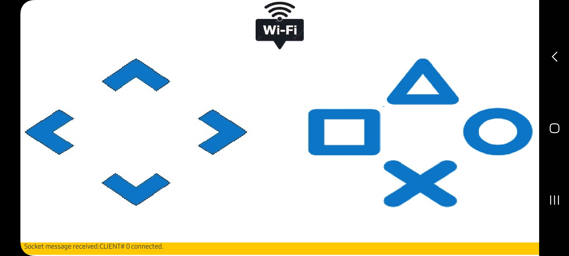
The message area at the bottom of the screen will indicate the assigned client ID#:

At the IDE end, the connection will look like the picture shown below:

When you are done, you can tap the WIFI icon again and terminate your connection.
¶ Use the Controls
Simply tapping the 8 control buttons will send the programmed commands to the ESP32.
Any messages
¶ WebSocket Use In APP Inventor
Here, we will examine the code of the APP Inventor APP and look at the WebSocket and project command implementation details. It is assumed that the user is familiar with the APP Inventor programming,
APP Code blocks:
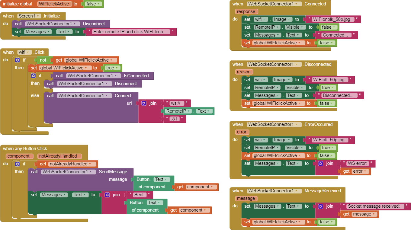
WebSocket in the APP is made possible by use of an extension: WebSocketConnector.

It provides a programming interface that supports the following events:
- Connection
- Disconnection
- Message Sending
- Message Reception
- Errors
¶ AI2 WebSocket Connection

For the Connection, we use the ESP32 server IP Address and the MicroBlocks Websocket port number 81: 192.168.1.48:81. The IP used may differ for your network due to WIFI configuration differences.
The IP address is extracted from the IP Address input field at the top of the APP GUI.

When the WIFI Icon is tapped, the APP initiates the connection via the script when WIFI.click.
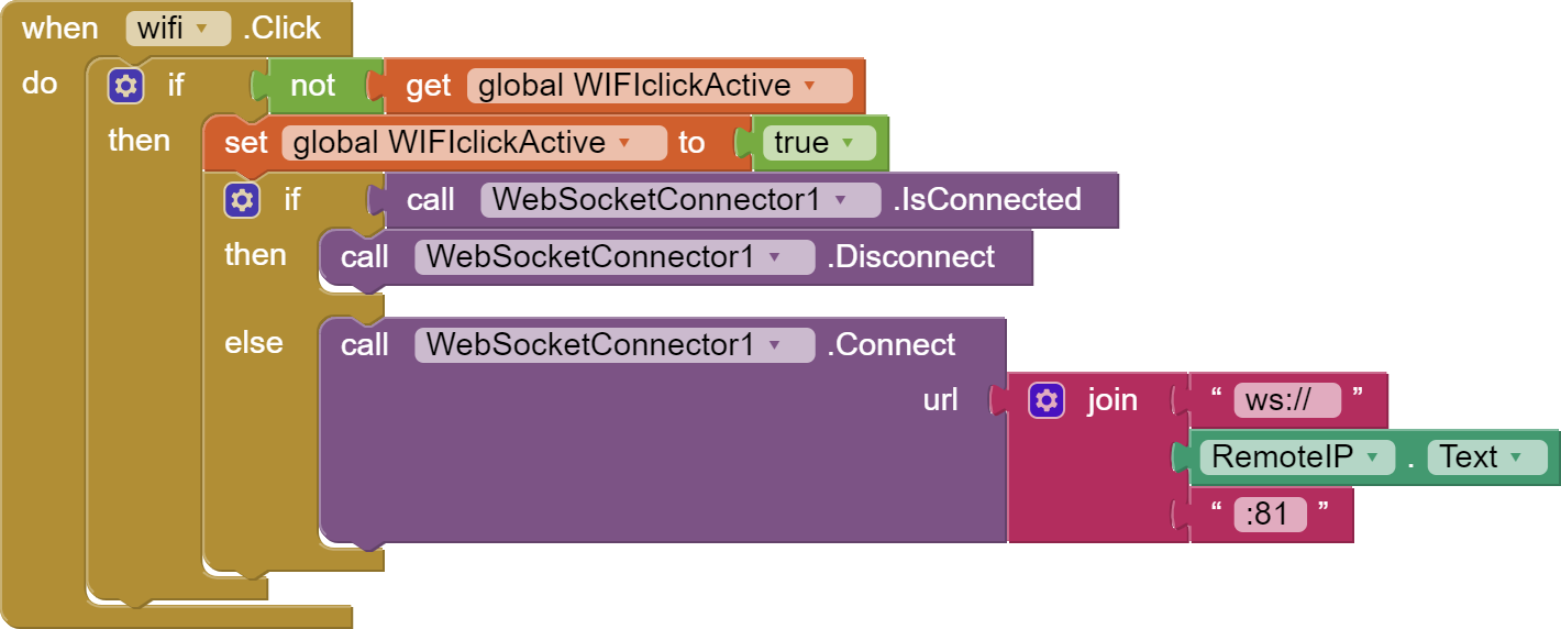
Above script handles the WIFI button click event. It is possible that one inadvertently generates multiple click events by tapping the icon back to back. This would normally cause multiple connections to be initiated; and create a problematic situation.
To prevent this, we implemented a boolean switch WIFIclickActive that controls the button clicks and their respective event handlers. Initially, this variable is set to false. As soon as a button is clicked, we set this variable to true and do not reset it untill all the related click event handling is completed. And the click events only are allowed while the switch is false.
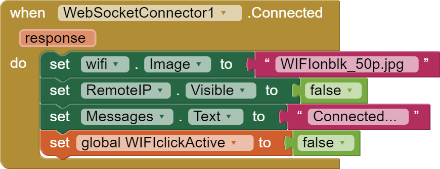
Upon a successfull connection establishment, when WebSocketConnector1 connected script is executed.
¶ AI2 WebSocket Disconnection

After a connection is established, if the WIFI icon is tapped a second time, the link is disconnected. See the code for when WIFI.click. script above. The WIFI icon button acts like a toggle switch: if there is no active WebSocket connection, then the connection is done. If the connection is active, then the link is disconnected.
 block provides the connection status.
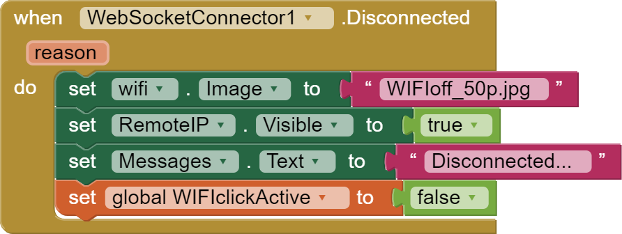
WebSocket link disconnection will cause the script when WebSocketConnector1 disconnected to be executed.
¶ AI2 WebSocket Message Send

Sending a WebSocket message is very simple; it only requires a message text.
Since we have eight different messages we need to send, we have resorted to a technique to reduce the number of blocks we need to code. Instead of using a standard approach of writing code for each of the eight button controls, we are using the generic code technique.
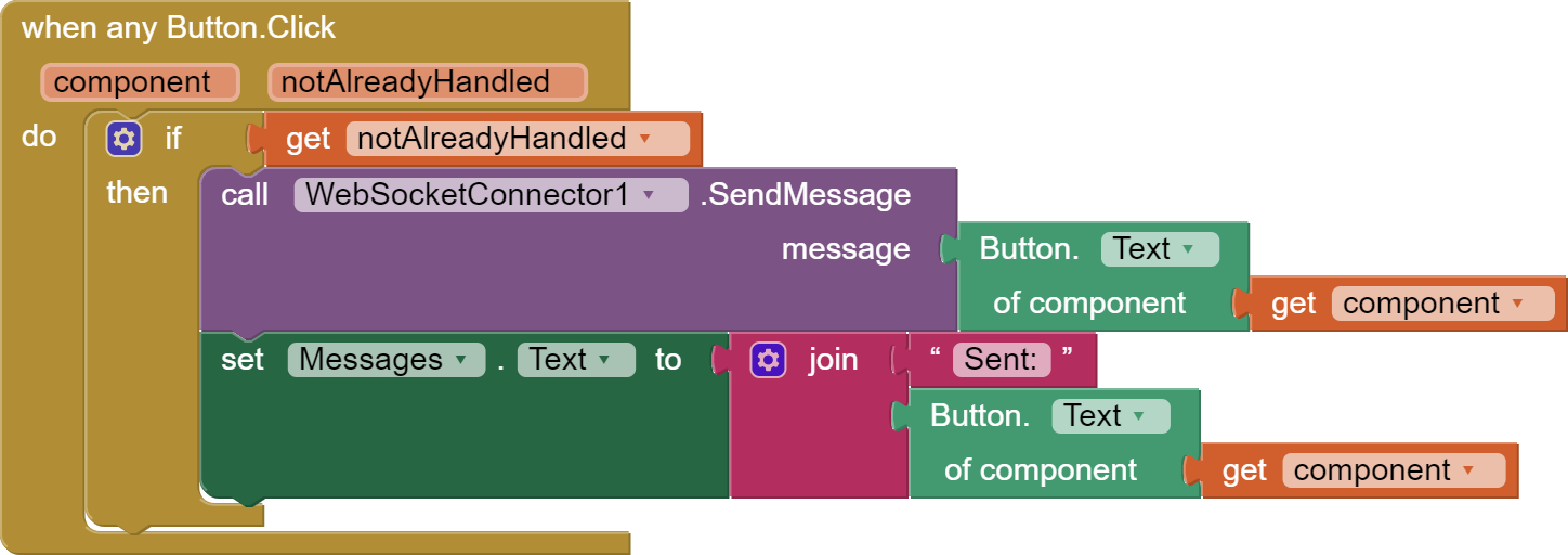
Since all our commands are activated by button clicks, we use the generic event when any Button.Click script. Code written in this script applies to any button clicked. And since all our command buttons do the same thing, it makes our lives easier.
To differentiate the different button actions, we have used another technique of labeling the buttons with their action names: left, right, up, down, square, triangle, cross, circle. This gives us the ability to use the button text names as the WebSocket message we need to send. And everything accomplished in a single script.
¶ AI2 WebSocket Message Receive

In this project, we do not receive any messages under normal operation conditions. However, it is possible to receive test message during testing of the project. To accomodate that case, we provide an event handler to display any incoming messages on the message area of the APP, at the bottom of the display.
¶ AI2 WebSocket Errors
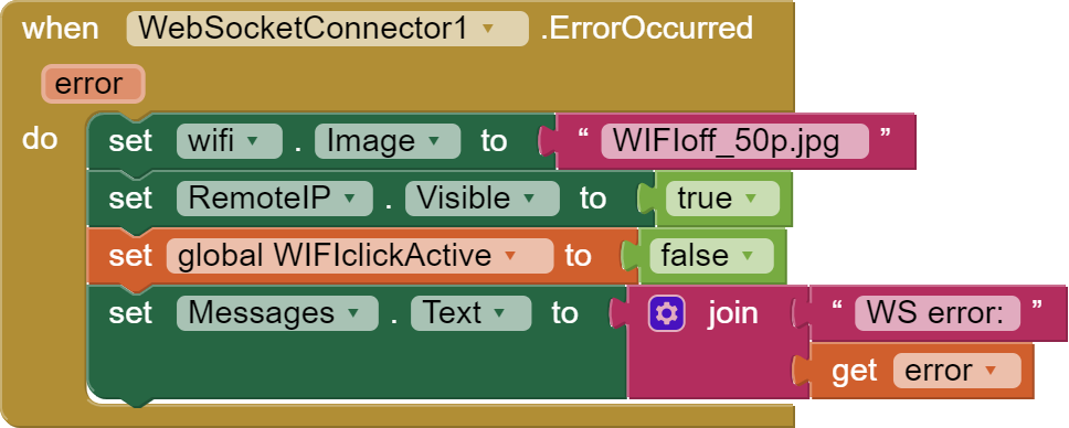
In case of any errors during the connection or normal operation of the APP, we provide an event handler to display any error messages on the message area of the APP, at the bottom of the display.
¶ No WIFI, No Problem - Let's fire up our HotSpot !
We have mentioned earlier that there may be cases where the environment you want to exercise control over your devices might not have a WIFI signal available. Specially, if you are in the woods or out in nature or in a far away from civilization location. No worries! You still will be able to experiment with this tutorial by following the directions provided here.
¶ My own WIFI Signal
Let's see how we can activate our own WIFI signal.
To create our own WIFI signal, we will need to select Button A after the program starts, or anytime we want to activate the Hotspot option.
¶ How Does it Work
To better visualize the HOTSpot setup, let's take a look at the picture below.
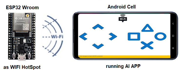
The ESP32 microcontroller is now acting as the WIFI Hotspot provider. It is running the same MicroBlocks program but with the startup option of Button A. The MicroBlocks program defaults to hotspotName = ESP32AP! and a hsPassword = 12345678. Feel free to change these to anything you want.
On the phone, you keep using the same APP.
¶ Let's Activate the new Network
When the ESP32 starts running and you press Button A, it will create a WIFI Network named ESP32AP. You can see this on your** PC WIFI network scan**, as well as your Android phone's WIFI scan. Here is what you should be looking for:
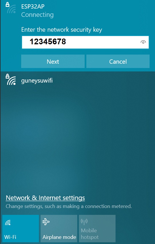
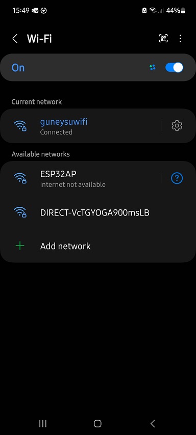
On the Android phone, under WIFI setting, you need to signon to the new network: ESP32AP / 12345678.
Now you can start using the APP the same way you were before. The top IP address needs to be set to the IP address of the HotSpot: 192.168.4.1 . You may get a different IP assigned with your hardware. Whatever is displayed, use that one.
There is no Internet access while you are in the HOTSpot mode.
If you have created a WIFI HotSpot and tested everything with it, remember to shut it down and login your devices and phone to your normal WIFI network. Otherwise, you will not be operating as you were before the exercises and wonder why nothing is working as usual.
¶ No Android Phone - Let's use PieSocket Websocket Tester
PieSocket is an extension of the Chrome browser. You can install it from the Chrome extension manager.
When you run it in the browser, it will look like the left picture below, with the exception of the Location data:
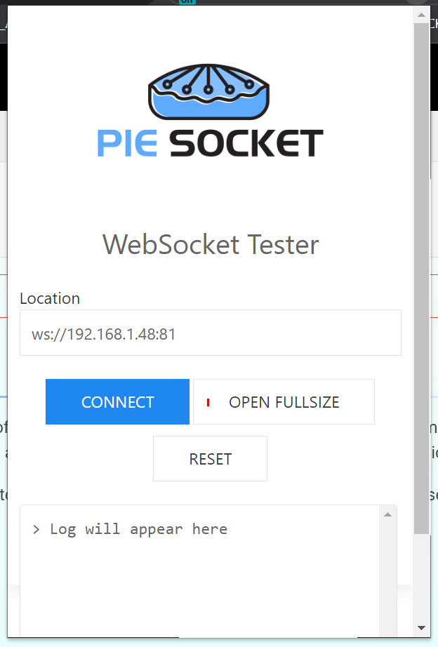
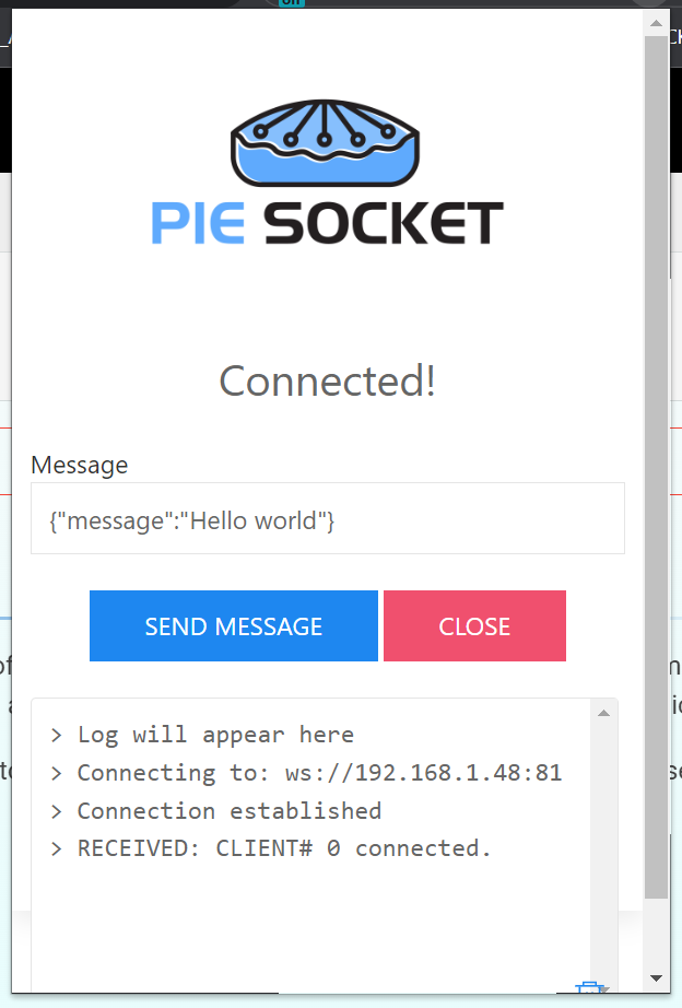
You need to enter the Server IP address in the format of the WebSocket protocol into the Location field: ws://192.168.1.48:81
When you click Connect, you will be presented with the right picture above. Please note the connection response message sent by the server: RECEIVED : Client# 0 connected.
The Client ID number displayed is your id number (0-4). When you observe the activity displays on the server, your actions will be reflected on the line with this Client number.
The testing process with the PieSocket is a bit different than using the APP Inventor companion program. Since all functions of the Server are controlled through straightforward text messages (commands), you simply enter the desired commands from the list below into the Location area and click Send Message.
Here is a list all the commands you can type and what they will be doing:
- left, right, up, down, square, triangle, cross, circle - Use one of these at a time. They will execute the respective programmed functions on the server.
- LED - will toggle on/off the user LED on the server.
- LOOP - will place your client port on the server into the Loopback mode. To get out of it, sent it again.
- any text message - anything other than the above listed commands will be treated as a normal message and displayed on the IDE. If the connectioon is in Loopback mode, they will be sent back to you.
¶ Discussion
This framework is provided as an example of implementing a GAMEPad style controller on the Android phones.
-
What type of projects do you think can use this control interface ?
-
What happens if the project we want to control has more than 8 commands ?
-
Understanding how the WEBSocket implementation in MicroBlocks works, can multiple people coordinate and use the controls ?
The Android APP is written in MIT's App Inventor. If you are familiar with MIT AI2, try the following challenges.
-
Some controllers have a set of four colored buttons instead of the geometrically shaped ones. Modify the interface to use colored buttons.
-
Expand the GAMEPad interface for two additional buttons.
The two challenges are of medium complexity and require a bit of know-how. If you manage to get them working, you have done extremely well.
¶ Pointers / Troubleshooting
In the first mode of the tutorial, where you are on your home network, you will normally see home network addresses in the range of 192.168.1.nnn. If for some reason you have modified your home Internet router to allocate a different range of IP addresses, then you may have addresses that look different.
If you are trying out the HotSpot version of the tutorial, you will need to be aware of the differences in IP addresses created and used.
In the HotSpot mode of the tutorial, the ESP32 will create a new network and dish out a different set of addresses. These will normally look like 192.168.4.1 for the router, and 192.168.4.2 and onwards for the other clients, including your Android phone.
In the HotSpot mode of the tutorial, remember to activate the new network first, on the ESP32 in our example. This will set up the environment ready to assign addresses for the joining devices. You should only hook up your phone's WIFI to the new network after you activate it. Otherwise, your phone WIFI scan will not see the network with the SSID = ESP32AP.
Keep in mind that during both operating modes of the tutorial, you are never accessing the Internet. As a matter of fact, in the Hotspot mode, there is not even any Internet connectivity available, as you will notice in the status displays of the WIFI networks. All traffic exchange happens within the private domain of your home network and of the new network you create with the HotSpot option.
There are ways to access the Internet under both operating modes. However, that is a very complicated topic to get into for the purposes of this tutorial. Anyone interested can research NAT (Network Address Translation), Proxy services, Private and public Internet addresses and try to make sense of it all.
A good way to get rid of the unwanted network entries in your PC and in your phone is to select the WIFI option to FORGET that network. You will find this option in the WIFI connectivity configuration section of your devices.
¶ What can go wrong
WebSocket protocol has built-in TIMEOUTs. If no protocol activity happens within the timeout period, the connection will be closed and any clients disconnected. There is no way to adjust the timeout period in the scope of this tutorial. So be aware of this and if you start seeing clients disconnecting, simply establish the connection again. Estimated time for the default timeout is about a minute.
Loopback mode is a very interesting operation mode. However, it may cause confusion with the user if the details of it workings are not understood exactly. Think of it as a switch that you set either ON or OFF. When it is ON, everything is sent back to the requesting party. Until you turn it OFF by selecting it again, it will stay in the Loopback mode.
And remember, in case of problems, the best way to restart everything is to RESET everything.
Enjoy!
¶ Project Download
GAMEPadWIFIRemote MicroBlocks Program For This Tutorial - Install on the ESP32.
MIT AI2 Android APP Source - Customize the APP using MIT AI2.
 |
MIT AI2 Android APP APK - Sideload this file to your phone. Might require permission to install unknown APPs. |
|---|