¶ Overview
Remote Control is a very handy technique used when controlling projects. Whether it is a robotic car, a house energy management system, or a weather station; they all could benefit from this communication / control method.
Remote Control can be implemented using any of the available communications capabilities of the microcontrollers at hand. Bluetooth, Serial Comms, GSM, RF, WIFI are methods that come to mind. In this tutorial, we will be specifically focusing on the use of WIFI based remote control, specifically one that makes use of the WebSocket Protocol.
And it is no surprise that we can learn how to make use of this technology with the help of MicroBlocks WIFI and Websocket Server Libraries. While other programming environments may offer the same functionality, MicroBlocks implementation is specifically simple and straightforward.
"The WebSocket protocol enables interaction between a web browser (or other client application) and a web server with lower overhead than half-duplex alternatives such as HTTP polling, facilitating real-time data transfer from and to the server. This is made possible by providing a standardized way for the server to send content to the client without being first requested by the client, and allowing messages to be passed back and forth while keeping the connection open. In this way, a two-way ongoing conversation can take place between the client and the server." - courtesy of Wikipedia.
We will learn how to transmit and receive WebSocket messages and act on the message content by turning an on-board LED on and off. Once you master this exercise, you can then implement other more complex control systems on your own.
To make things more interesting and also to showcase one of the greatest features of MicroBlocks - PARALLELISM / MULTITASKING, this tutorial will run supporting up to five users at the same time, all doing different things on the same server.
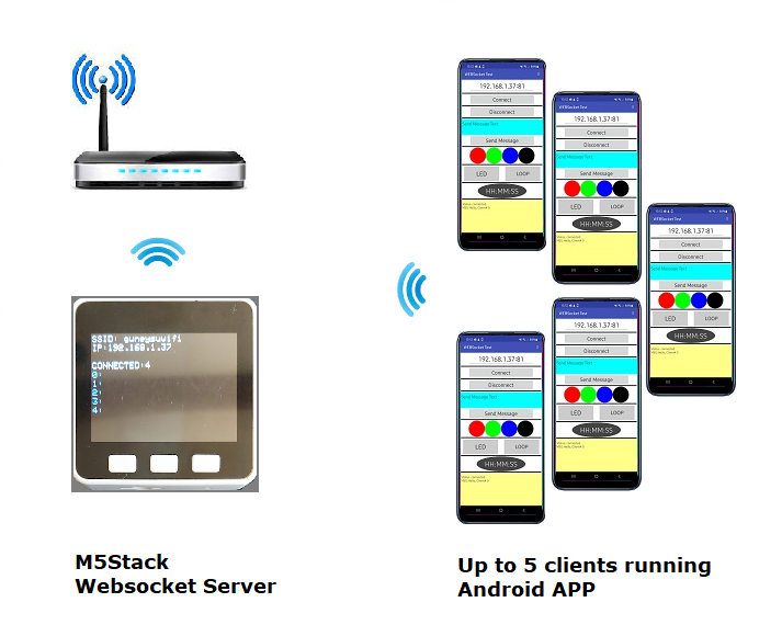
Microcontrollers that can be used in this project should have several common features:
- they should support WIFI
- they should have an on-board LED
- they should have a COLOR display to make program actions easier to observe
In the picture below, we show M5Stack microcontroller with an integrated COLOR display. You may have other suitable choices available to you.
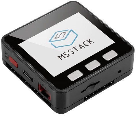
In addition to the MicroBlocks demo program, we will also provide you with a demo program for an Android phone, so you can use it as a remote control device to participate in this exercise and to send and receive messages. The APP allows you to experiment with many remote control options:
- sending and receiving messages
- controlling a simulated RGB LED
- Stream time of day clock info
- Exercise looping of socket connections, thus enabling you to control your own phone.
¶ Parts
To complete this tutorial you will need:
-
a M5Stack
-
an Android Phone
-
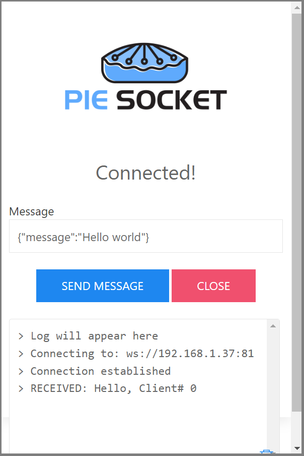
If you do not have an Android phone, then you can install the PieSocket WebSocket Tester extension for Chrome and work with that.
¶ Making the connections
Since this exercise makes use of the WIFI capability of the device in use, there will be no need for physical cabling.
As far as the WIFI availability goes, you can start by using the WIFI provided by your house router.
You can also create your own WIFI HotSpot using the the M5Stack and provide your own WIFI signal. This will be handy if you plan on operating in an area without a WIFI service present.
¶ Scripts
MicroBlocks project is coded in the program WebSocket Demo.ubp.
M5Stack, acting as a server, is programmed to:
- Act as a WIFI client on the local wireless network or become a HOTSpot providing a WIFI AP service
- support up to five clients, all operational
- send, receive, and display messages
- turn on and off the User LED on the microcontroller
- simulate four different colored LEDs
- place each socket into loopback mode
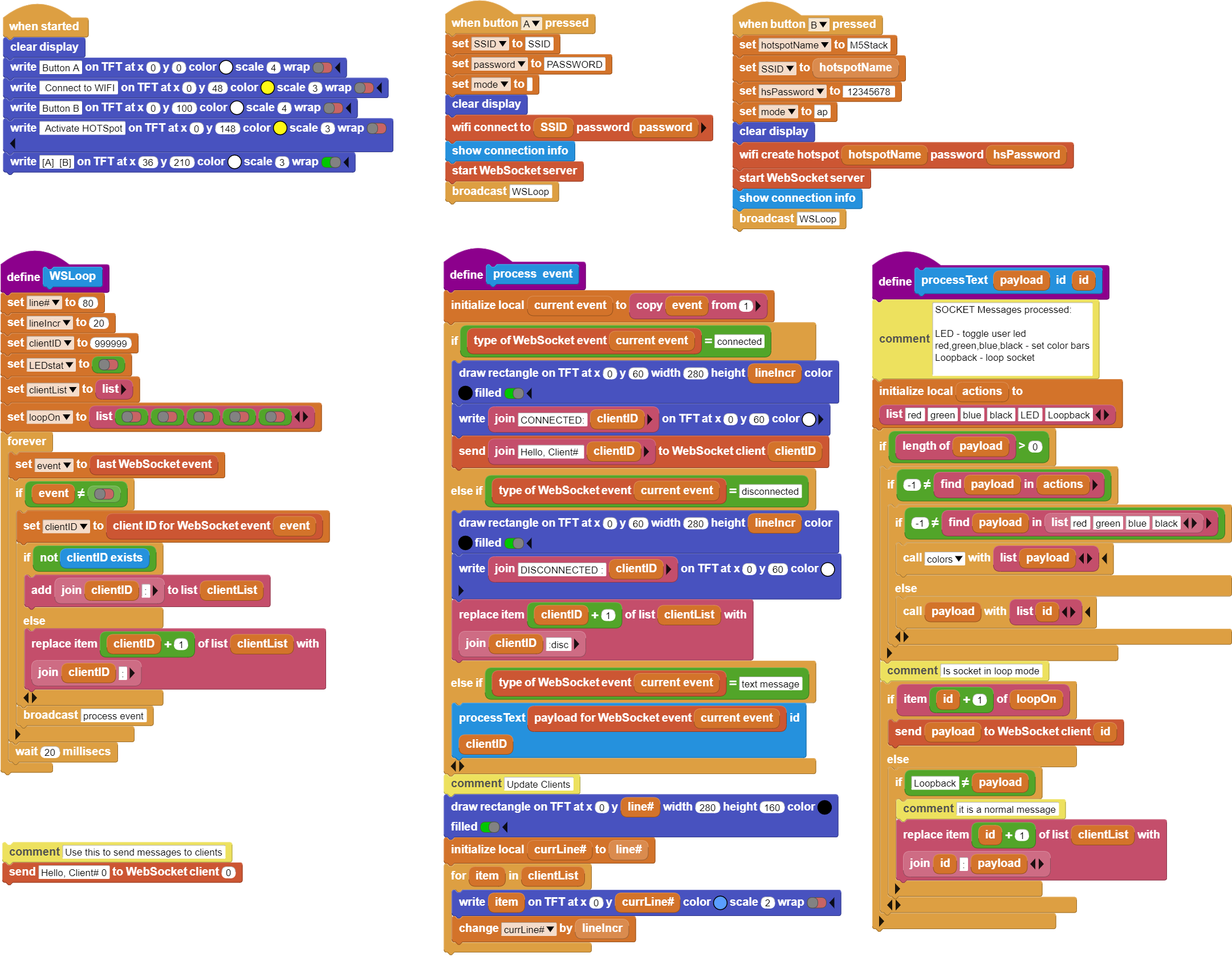
In the project scripts picture below,
-
when started block displays the two running options: Connect to WIFI and Activate HOTSpot.
-
when button A pressed handles the setup for local WIFI connection. Displays the connection information and starts WSLoop to process Websocket messages.
-
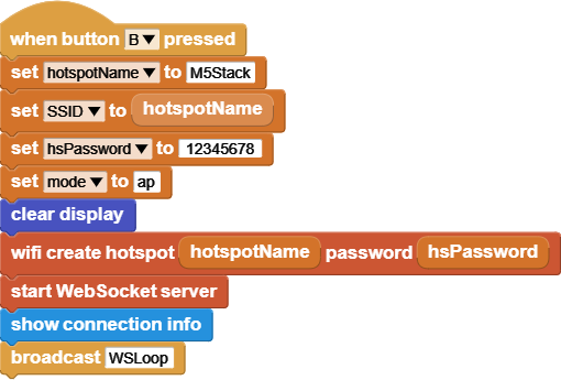
when button B pressed handles the setup for HOTSpot mode. Displays the connection information and starts WSLoop to process Websocket messages.
-
WSLoop sets up the project variables and then the script enters a loop of receiving messages and dispatching them to the process event logic to be handled. Incoming mesages are checked for new client connections, If found, it will add it to the clientList variable to keep track of it.
-
process event script deciphers the WebSocket connect, disconnect, and text message payload types. Text message payloads are dispatched to processText script to be handled.
-
processText script handles all the main messages of the program. Depending on the payload received, different scripts are executed to proces the incoming messages.
There are other scripts in the My Blocks section of the IDE that are used to perform the lower level details of the messages and necessary display actions.

This project supports up to five remote clients connecting to the WebSocket server. This script verifies each received message to check if the client already exists. It will return true or false depending on the status of the client.

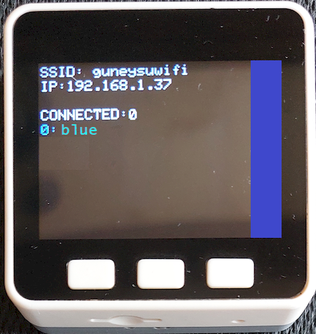
This script handles the display of the simulated RGB LED. Simulated RGB LED is a rectangular area at the right edge of the screen. It is set to one of red, green, blue, or black colors, depending on the message received.

This script is used to turn the on-board LED on and off.

Each socket of the WebSocket server is independently controlled and looped back when the Loopback command is received. This enables the user at the Android phone end to send messages to the server and have the server send them back. The received messages are acted upon at the phone end.

When the server signs on to the local WIFI network, it obtains an IP address. This script displays the SSID and the obtained IP address.

When you are testing your project, you can use the WebSocket send block to send a message to a client on a specific socket number.
In order to do that, you need to make a note of the displayed Client ID at the phone APP when a connection is made. Then direct your message to that specific client number using this block.
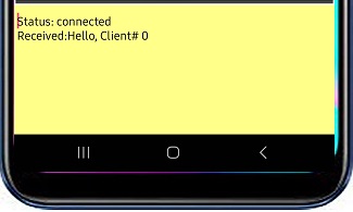
On the Android APP, client ID will be displayed in the messages area of the display.
¶ Process
This project requires an Android APP running on an Android phone or similar device, and the MicroBlocks WebSocket Demo program running on the M5Stack microcontroller. M5Stack is acting as the Server and the Android device is the Client.
Remember to replace the SSID and Password in the MicroBlocks program with your specific information.
It may be helpful to briefly review the WebSocket Protocol (WS) operations to get a better feel for all the action in our tutorial. You can refer to the Websocket article in Wikipedia or else for a more detailed treatment of the topic.
¶ WebSocket Basics
(courtesy of Wikipedia and web.dev)
The WebSocket protocol enables interaction between a web browser (or other client application) and a web server with lower overhead than half-duplex alternatives such as HTTP polling, facilitating real-time data transfer from and to the server.
This is made possible by providing a standardized way for the server to send content to the client without being first requested by the client, and allowing messages to be passed back and forth while keeping the connection open. In this way, a two-way ongoing conversation can take place between the client and the server.
The communications are usually done over TCP port number 443 (or 80 in the case of unsecured connections), which is beneficial for environments that block non-web Internet connections using a firewall.
Sockets
The WebSocket specification defines an API establishing "socket" connections between a web browser and a server. In plain words: There is an persistent connection between the client and the server and both parties can start sending data at any time.
¶ WebSockets in our Project
MicroBlocks implementation of the Websocket protocol is manifested in the WebSocket server Library. It uses port number 81.
There is no special requirement prior to using the protocol, other than devices involved have to be present on a shared IP network, in our case our local WIFI.
Let's review the library blocks used:

Once the WIFI signon is completed and an IP adress is obtained from the local router, this block initiates the WebSocket server.

Each message the protocol receives is considered an event. This object is used in other blocks below to link and decipher the event and its content parts.

Every connection that is established between the server and the client gets assigned a socket number, which is also called client id (0-4). Max for MicroBlocks is 5 clients.

This is the actual content of the message received.

WebSocket messages are classified as events. There are several:
error, disconnected, connected, text message, binary message, text fragment start, binary fragment start, fragment, fragment end, ping, pong, waiting
In this tutorial, we are mainly concerned with connect, disconnect, and text message.

With this block, we can send a message to any client that is connected to the server, by using its client id.
¶ App Inventor APP
We have provided an Android companion APP for the MicroBlocks WebSocket Demo program. It will provide you with some flexibility if you only have a microcontroller with no display to work with. You can place the server in loopback mode and just send messages from the phone to itself.
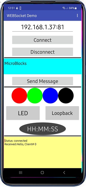
Below image displays the APP GUI at the start of the program, right after it has connected to the Server.
¶ APP User Interface
The APP GUI consists of four parts:
-
IP / Connect / Disconnect: used to enter the server IP address and connect and disconnect to/from it. Make sure the IP address you enter is followed by a ":" and WebSocket port number 81 (MicroBlocks requirement), eg: 192.168.1.40:81
-
Message Send Area: Enter any text and tap Send Message to send it to the server.
-
Program Actions Area: This area contains all the buttons for the remote control of the server:
- Four simulated RGB LED buttons
These are used to color the right edge of the server display in four different colors. - User LED control button
Will turn on/off the user LED on the server - Loopback button
Will place each respective client port into loopback mode.
In this mode, all messages sent to the server are sent back and will be acted on by the APP. - Current time of Day button
This will start sending out the current time in HH:MM:SS format to the server.
Update frequency is every second.
- Four simulated RGB LED buttons
-
Message Display Area: All exchanges of the program and any error messages are displayed in this area.
¶ How to Use the APP
The APP GUI provides a simple interface to all the functions of the program. Let's break it down to various tasks and try it out:
¶ Connect to the Server
When you start the MicroBlocks program on the M5Stack Server with Button A selection, it will signon to your in-house WIFI and obtain an IP address; most likely in the format of 192.168.n.n or similar depending on your network configuration.
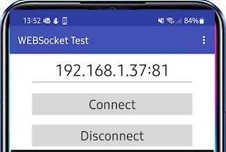
You need to write this IP address down and enter it into the IP address area of the phone APP, at the very top of the display. You then tap the Connect button and observe your phone estabish a WebSocket connection to the server.
You will recognize a successful connection when you receive a greeting from the Server: Received: Hello, Client#0.

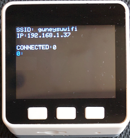
At the server end, the connection will look like the M5Stack picture shown above.
When you are done, you can press the Disconnect button and terminate your connection.
¶ Send a WebSocket Message
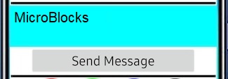
You need to enter the message content into the cyan colored message area. Then you can tap the Send Message button. Your message should arrive at the Server and display next to the cliend ID number that is assigned to you.
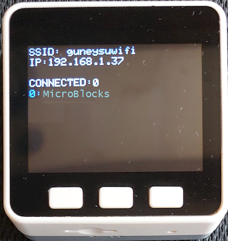
Each client's messages will be displayed on its own line, with the client id preceeding it.
¶ Control the simulated RGB LEDs
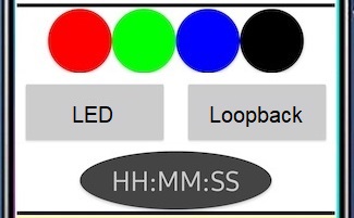
There is nothing special to do here but tap the colored circles representing the LEDs. A message wth payload red, green, blue, black (depending on your choice of button you pressed) will be sent to the Server. You will observe the right edge of the Server display light up in the color of the circle you have pressed. Picture below depicts the result of button blue pressed.
¶ User LED on/off
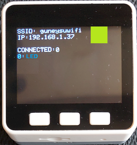
When you tap the LED button, a message with payload LED will be sent to the Server. The Server will respond by turning on / off the user LED at location 5,1 of the display matrix.
¶ HH:MM:SS
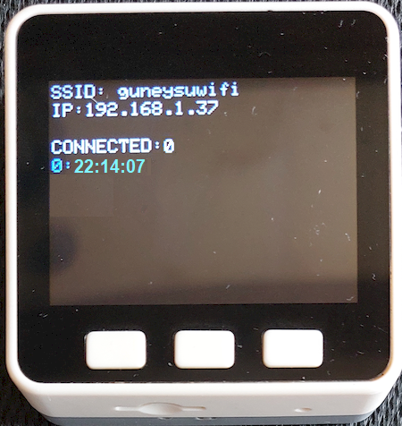
This button starts sending continuous messages to the Server at one second intervals. The payload is the time of day. The time display on the button will show the digits for the TOD message.

Same message content will be displayed at the Server side at the corresponding client id line.
¶ Loopback
This function puts the server's client id port into loopback, meaning it will send back everything it receives on that port. This will allow the users to test the WebSocket concepts even if they do not have a M5Stack. Server display will look like:
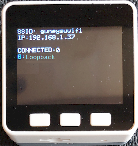
The behavior of the APP functions are a bit different when the loopback is engaged. Please refere to the picture below as you read the descriptions of the display changes in the Loopback mode. The message area will display all the commands as they are received back from the server.
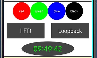
Here are all the display related differences in loopback mode:
Loopback: The button will send the payload Loopback and receive it back. Acting on the incoming command, it will change the color of the button background to dark gray and the text color will be white. Message area will display Received:Loopback.
Send Message: If you send a message, message text will be sent back and appear in the message area of the APP as Received:'message text'
LED: Similar to the Loopback button, the colors will change to white text on dark gray background. Message area will display Received: 'color name'.
Colored LED Control Buttons: as you press each button its color name will display in white when it is activated, and revert to no color name displayed when pressed a second time. Message area will display Received:'color name'.
HH:MM:SS : current time will be displayed on the button and sent to the Server. The loopback mode will send the same message back and it will be displayed in the message area as Received:HH:MM:SS. You may notice a delay or slight difference in displayed times if the APP to Server link has a latency over a second.
When you are in Loopback mode and you have activated the time display, the APP will be sending a time message every second. It will be sent back and displayed in the message area. If at the same time you try one of the other functions described above, you will not see their returned responses in the message area, as they will be quickly overwritten by the time display.
¶ No WIFI, No Problem - Let's fire up our HotSpot !
We have mentioned earlier that there may be cases where the environment you want to exercise control over your devices might not have a WIFI signal available. Specially, if you are in the woods or out in nature or in a far away from civilization location. No worries! You still will be able to experiment with this tutorial by following the directions provided here.
¶ My own WIFI Signal
Let's see how we can activate our own WIFI signal.
To create our own WIFI signal, we will need to select Button B when the program starts, or anytime we want to activate the Hotspot option.
¶ How Does it Work
To better visualize the HOTSpot setup, let's take a look at the picture below.
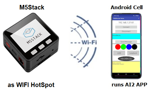
The M5Stack microcontroller is now acting as the WIFI Hotspot provider. It is running the same MicroBlocks program but with the startup option of Button B. The MicroBlocks program defaults to hotspotName = M5Stack and a hsPassword = 12345678. Feel free to change these to anything you want.
On the phone, you keep using the same APP.
¶ Let's Activate the new Network
When the M5Stack starts running and you press Button B, it will create a WIFI Network named M5Stack. You can see this on your** PC WIFI network scan**, as well as your Android phone's WIFI scan. Here is what you should be looking for:
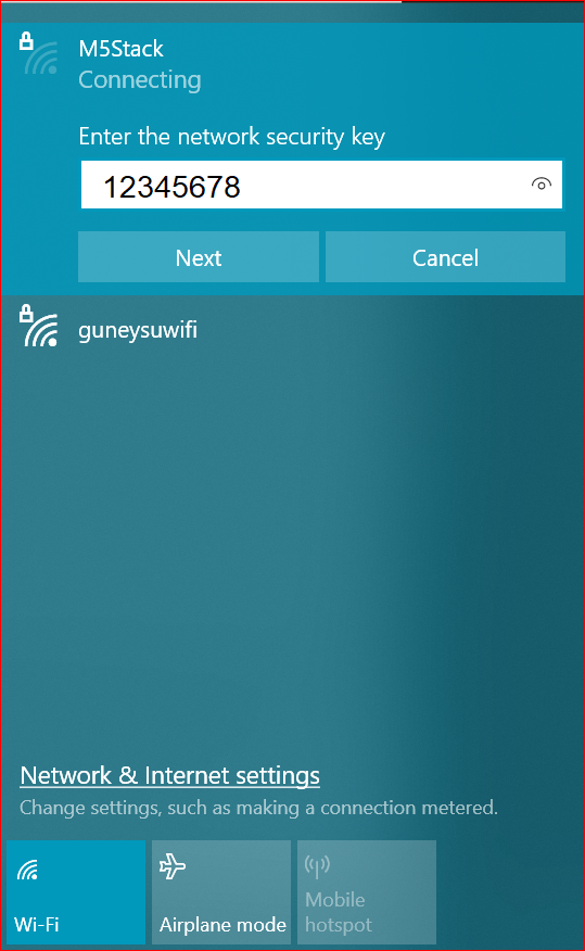
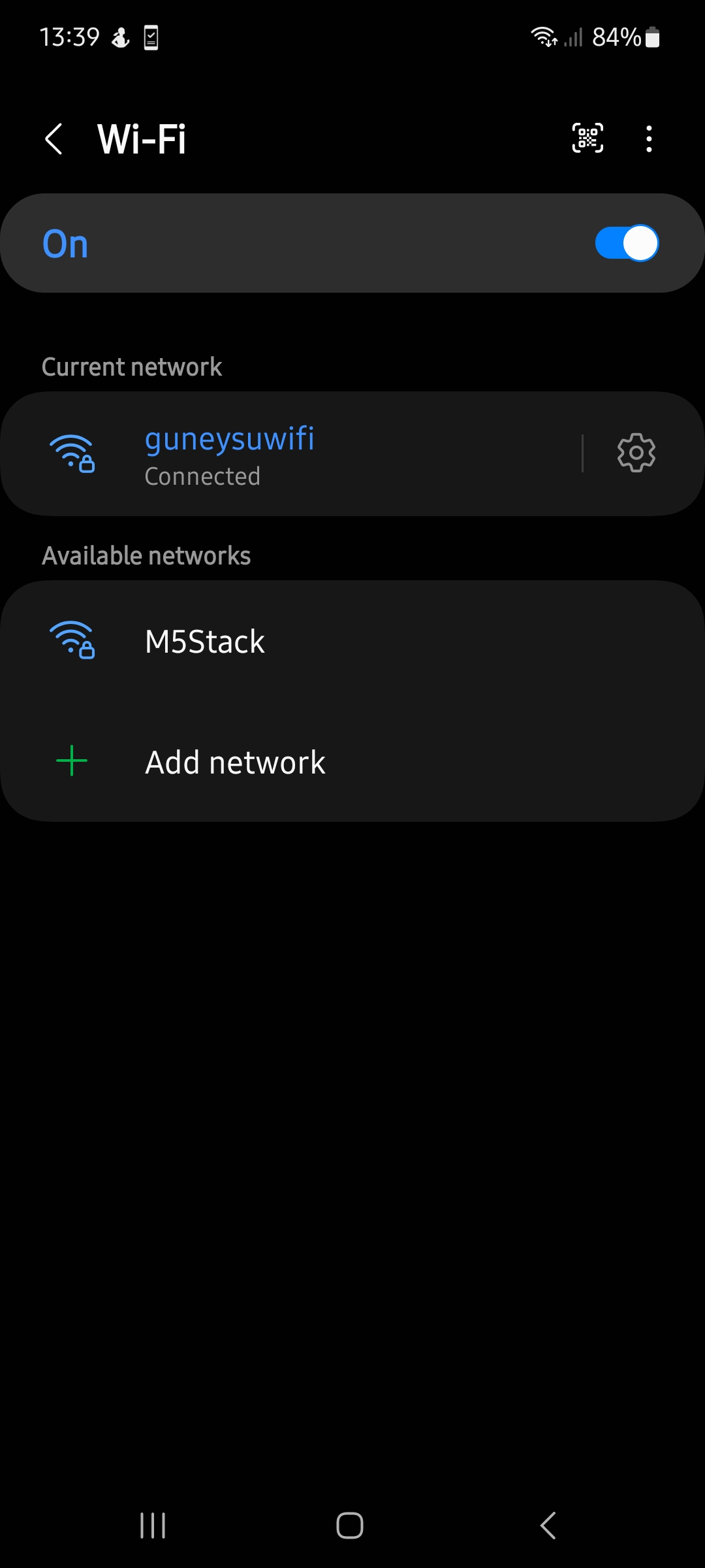
On the Android phone, under WIFI setting, you need to signon to the new network: M5Stack / 12345678.
Now you can start using the APP the same way you were before. The top IP address needs to be set to the IP address of the HotSpot: 192.168.4.1 . You may get a different IP assigned with your hardware. Whatever is displayed, use that one.
There is no Internet access while you are in the HOTSpot mode.
If you have created a WIFI HotSpot and tested everything with it, remember to shut it down and login your devices and phone to your normal WIFI network. Otherwise, you will not be operating as you were before the exercises and wonder why nothing is working as usual.
¶ No Android Phone - Let's use PieSocket Websocket Tester
PieSocket is an extension of the Chrome browser. You can install it from the Chrome extension manager.
When you run it in the browser, it will look like the left picture below, with the exception of the Location data:
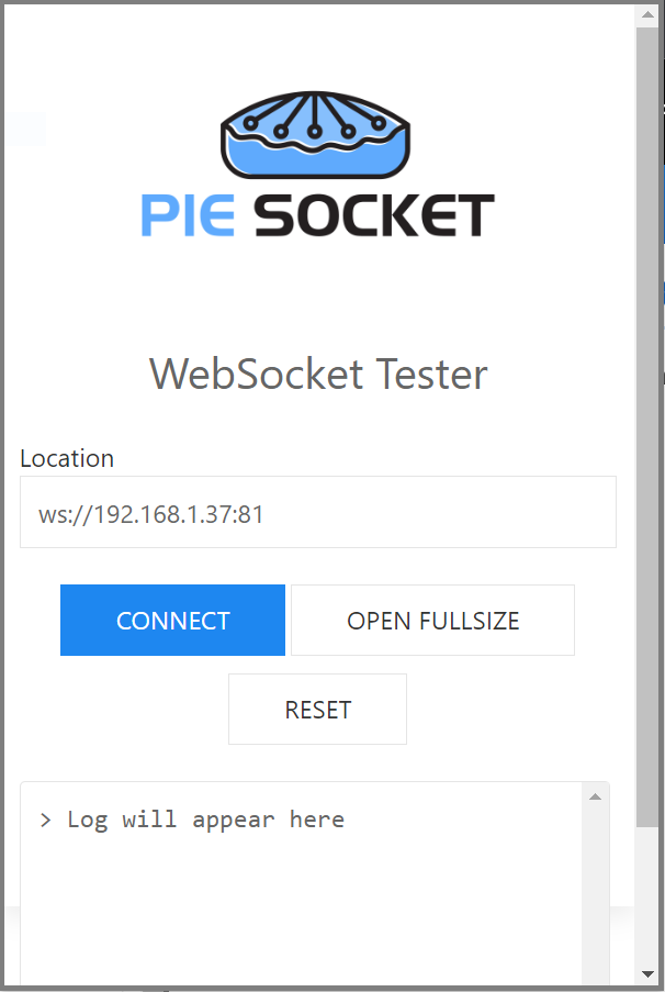

You need to enter the Server IP address in the format of the WebSocket protocol into the Location field: ws://192.168.1.37:81
When you click Connect, you will be presented with the right picture above. Please note the connection response message sent by the server: RECEIVED : Hello, Client# 0.
The Client ID number displayed is your id number (0-4). When you observe the activity displays on the server, your actions will be reflected on the line with this Client number.
The testing process with the PieSocket is a bit different than using the APP Inventor companion program. Since all functions of the Server are controlled through straightforward text messages (commands), you simply enter the desired commands from the list below into the Location area and click Send Message.
Here is a list all the commands you can type and what they will be doing:
- red, green, blue, black - Use one of these at a time. They display the respective colored rectangle on the server.
- LED - will turn on/off the user LED on the server.
- Loopback - will place your client port on the server into the Loopback mode. To get out of it, sent it again.
- any text message - anything other than the above listed commands will be treated as a normal message and displayed on the server display. If in Loopback mode, they will be sent back to you .
It is not possible to generate Time of day stream in this operation mode. However, you can type any text message that has a different content than the commands listed above, and it should be sent to the server. And if the server is in the Loopback mode, then you will see tham sent back to you.
You can run multiple sessions of the PieSocket from the browser and each one will be assigned a different Client ID number, allowing you to test with multiple Clients on the Server.
¶ Discussion
WebSocket protocol operates on top of the TCP protocol. As such, it maintains the integrity of the submitted messages. Compare this to the UDP messages, which are not guaranteed for delivery.
Operating the M5Stack, you can press Button A and Button B any time to switch between the two operating modes: Local WIFI and IP HOTSpot.
What do you think is the longest message you can send?
The Android APP is written in MIT's App Inventor. If you are familiar with MIT AI2, try the following challenges.
-
Current project toggles a SINGLE simulated built-in LED on the server. Therefore in tests with multiple clients, the actions on the LED will reflect the cumulative effects of the clients. How would you modify the project to implement a simulated user LED for each client separately?
-
If you managed to achieve the above challenge, you could also implement a simulated RBG LED for each client, instead of a single one shared by all clients.
Last two challenges are pretty complex and require quite a bit of know-how. If manage to get them working, you have done extremely well.
¶ Pointers / Troubleshooting
In the first mode of the tutorial, where you are on your home network, you will normally see home network addresses in the range of 192.168.1.nnn. If for some reason you have modified your home Internet router to allocate a different range of IP addresses, then you may have addresses that look different.
If you are trying out the HotSpot version of the tutorial, you will need to be aware of the differences in IP addresses created and used.
In the HotSpot mode of the tutorial, the M5Stack will create a network and dish out a different set of addresses. These will normally look like 192.168.4.1 for the router, and 192.168.4.2 and onwards for the other clients, including your Android phone.
In the HotSpot mode of the tutorial, remember to activate the new network first, on the M5Stack in our example. This will set up the environment ready to assign addresses for the joining devices. You should only hook up your phone's WIFI to the new network after you activate it. Otherwise, your phone WIFI scan will not see the network with the SSID = M5Stack.
Keep in mind that during both operating modes of the tutorial, you are never accessing the Internet. As a matter of fact, in the Hotspot mode, there is not even any Internet connectivity available, as you will notice in the status displays of the WIFI networks. All traffic exchange happens within the private domain of your home network and of the new network you create with the HotSpot option.
There are ways to access the Internet under both operating modes. However, that is a very complicated topic to get into for the purposes of this tutorial. Anyone interested can research NAT (Network Address Translation), Proxy services, Private and public Internet addresses and try to make sense of it all.
A good way to get rid of the unwanted network entries in your PC and in your phone is to select the WIFI option to FORGET that network. You will find this option in the WIFI connectivity configuration section of your devices.
¶ What can go wrong
WebSocket protocol has built-in TIMEOUTs. If no protocol activity happens within the timeout period, the connection will be closed and the Client disconnected. There is no way to adjust the timeout period in the scope of this tutorial. So be aware of this and if you start seeing clients disconnecting, simply establish the connection again. Estimated time for the default timeout is about a minute.
The project programs are written to toggle the LEDs. This means that there is no forced way to set a LED to a desired state: ON or OFF. In the beginning of the programs, all LEDs are OFF. But as the exercises continue, they may get out of synch due to actions by multiple clients. So any LED's subsequent behavior is totally dependent on what state it was in just before the last message arrived.
Loopback mode is a very interesting operation mode. However, it may cause confusion with the user if the details of it workings are not understood exactly. Think of it as a switch that you set either ON or OFF. When it is ON, everything is sent back to the requesting party. Until you turn it OFF by selecting it again, it will stay in the Loopback mode.
Time of display messages sent from the APP are generated every second. If you are in Loopback mode with the Time messages generating, you will not see the results of any OTHER functions that you may attempt, displayed in the message area. Time displays will overwrite them quickly. However, they do happen and get processed by the APP. Simply stop the Time displays and you'll start seeing the other messages.
And remember, in case of problems, the best way to restart everything is to RESET everything.
Enjoy!
¶ Project Download
WebSocket Demo MicroBlocks Program For This Tutorial - Install on the M5stack.
MIT AI2 Android APP Source - Customize the APP using MIT AI2.
MIT AI2 Android APP APK - Sideload this file to your phone. Might require permission to install unknown APPs.
 |
MIT AI2 Android APP APK - Sideload this file to your phone. Might require permission to install unknown APPs. |
|---|