¶ Overview
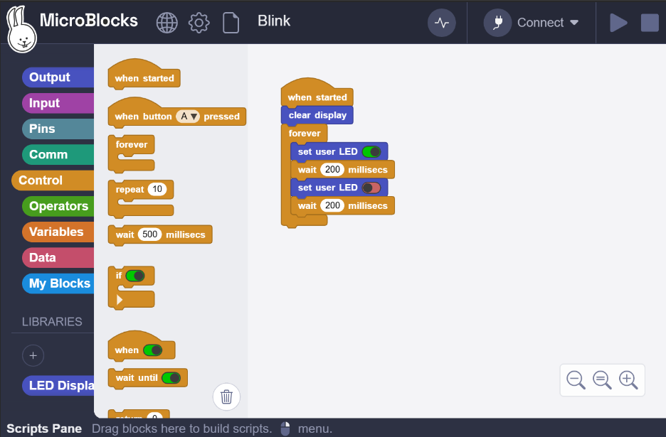
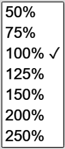
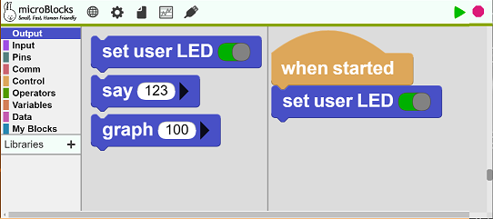
The picture below shows the principal areas of the MicroBlocks editor.
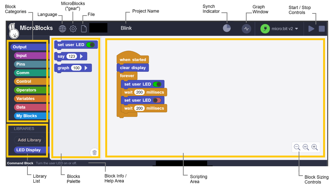
The IDE is organized in six principal areas:
- Block Categories on the left top
- Libraries on left bottom
- Blocks Palette in the middle
- Scripting area on the right side
- Block Info and Help area at the bottom of the display
- Menu and Control icons at the very top
In addition, there are Block Sizing controls placed on the bottom right of the IDE Scripting Area.
¶ Block Categories
This area contains all the block categories that are used to program in MicroBlocks. They are grouped in nine color-coded groups. As categories are selected, corresponding blocks in that category will be listed in the Blocks Palette area next to it.
For a detailed description of all the blocks, please refer to the Blocks Reference.
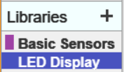
¶ Library List
The contents of this area reflects the various libraries that are loaded depending on the requirements of the user scripts and micro devices. It could range from totally empty to quite a few. For a detailed description, see Libraries below.
¶ Blocks Palette
As selections are made in the Block Categories area, blocks with those specific functionalities will be listed in this area. From here, the blocks are dragged and dropped onto the Scripting Area to write programs.
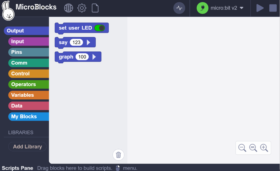
If blocks in the Scripting Area need to be deleted, they can be simply dragged into this area. A trashcan icon is visible at the bottom of this area to indicate this possibility.
![]()
![]()
If a Custom Block Definition in the Scripting Area is moved to this area, it will not be deleted, but rather hidden.
¶ Scripting Area
This is the main surface of the MicroBlocks environment where all the coding activities occur. Blocks are dragged and dropped onto this area to build up user scripts and custom blocks (functions).
¶ Block Info / Help Area
As the mouse is moved over the various blocks and IDE areas highlighted in yellow, this area displays the type of the block and a short help info about the blocks; as well as the functionality of the various areas. Detailed block Help information is available through the right-click menu of each block.
¶ Block Sizing Controls
These three controls enable one to resize the blocks up (+) or down (-), as well as set them to the default (=) size.
¶ Menu Bar
Located at the very top of the display area, it displays Language, MicroBlocks (gear), and File icons. Project Name is displayed when one is loaded. Synch Indicator, Graph and Connection icons are followed by Start and Stop Controls. These are described in detail below.
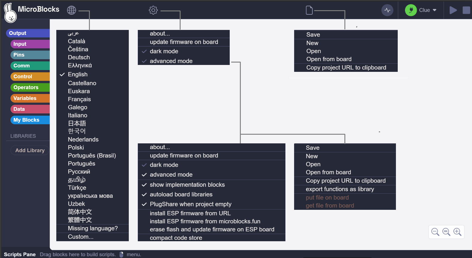
Selecting advanced mode from the MicroBlocks (gear) menu makes some additional blocks appear in the palette. It also enables additional features and menu options needed by more advanced users.
Image below displays the normal mode and advanced mode menus for these three icons all together.
¶ Menu Descriptions
The sections below describe in detail all the contents and functionality of the menus.
The first three icons present drop-down menus when clicked.

¶ Language

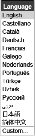 |
This menu item allows the user to select one of the many languages the MicroBlocks editor is translated into. Once set, all menus, messages, and code blocks will be presented in that language. |
|---|
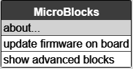
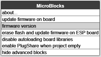
¶ MicroBlocks ("gear")

In the normal setting, this menu controls the following:
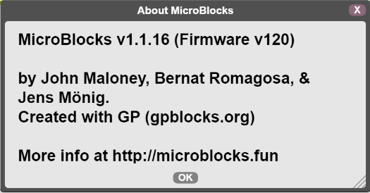
about...
Displays information about the MicroBlocks editor and virtual machine Firmware versions for the micro device.
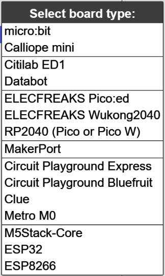
update firmware on board
This item enables the user to load the latest version of the firmware to the micro device attached.
Depending on the conditions, a device selection menu may be presented for the user to choose from.
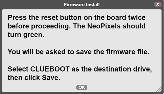
After the selection, different messages prompting for further actions will be displayed.
MicroBlocks supports many microcontroller boards. See Boards section for detailed information.
Here are some sample prompts for the Adafruit CLUE device:
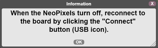
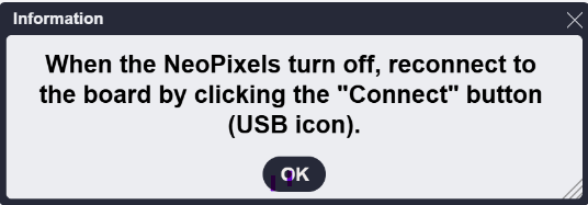
As the firmware update proceeds, the green USB icon will be off. Upon completion of the update, the connectivity between the micro device and the USB port needs to be reestablished. See USB section.
MicroBlocks supports many devices, but still many are not in the internal devices list. If you do not see your device listed here, check out one of the other firmware update options listed further below.
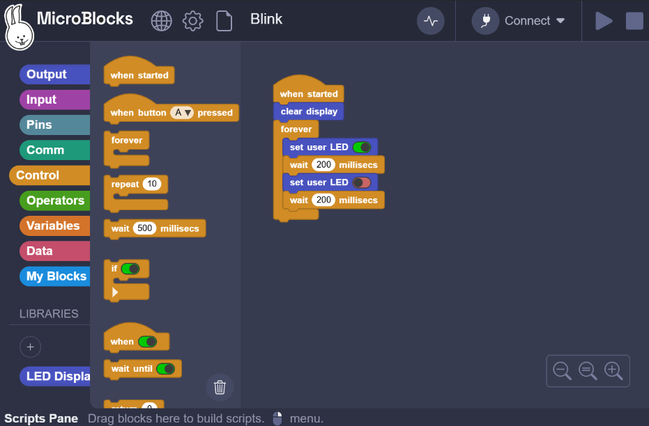
dark mode
Enables the user to select light and dark themes for the IDE visuals. A sample of both are provided below.
advanced mode
When selected, the advanced options in the menus, as well as advanced blocks in the Block Categories will be enabled.
If advanced mode is enabled, the menu item will display a checkmark next to its name.
¶ MicroBlocks ("gear") Advanced
In the advanced mode setting, this menu controls the following:
show program size on board
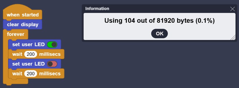
Displays the amount of memory the program occupies when loaded onto the board.
The board must be connected to the IDE and a program has to be loaded into the IDE for this option to show up in the advanced manu options.
The code store is the persistent memory on the board that stores your program. This command also compacts the code store and prints the amount of space used and available in the Javascript console. It may take a few seconds to run.
When working with large programs and libraries it is sometimes useful to know how much space is being used. That can guide you if you want to shrink your program to decreaes loading time or free up space for additional code.
The code store is automatically compacted as you work, so this command is only needed if you need to know how much space your program consumes.
show implementation blocks
When selected, both variables and custom blocks that start with an "_" (underscore) in the block palette will be shown. Usually, these items are either advanced use items or are used internally by the scripts that define them.
autoload board libraries
One of the niceties of the MicroBlocks editor is, that it always tries to make things simpler for the users. Since every micro device has different characteristics, features, and capabilities, MicroBlocks automatically tries to supplement the basic functionalities by loading various libraries.
Here, as an example, are two libraries loaded for the micro:bit device:
When not selected, this item disables this functionality; and it is up to the user to load the required libraries.
open VM folder on microblocks.fun
This menu option displays the VM firmware download page on the microblocks.fun web page.

MicroBlocks supports many devices, but still many are not in the internal devices list. Any of the listed VM firmware files shown here can be retrieved and downloaded to the user's PC. From there, it can be transferred to the attached micro device by dragging and dropping it; thus updating the firmware of that device
Install ESP firmware from URL
MicroBlocks supports many ESP devices, but still many are not in the supported devices list. Whenever someone creates a custom VM for one of these and stores it somewhere on the Internet, this feature can be used to retrieve and load it to the attached device.
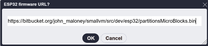
Once the URL is entered and OK is clicked, the firmware will be downloaded and installed on the device.
When the update is completed, you may be asked to reestablish the USB connectivity. See USB section.
Install ESP firmware from microblocks.fun
Microblocks website has several precompiled VMs for various micro devices. These can be downloaded and installed using this option.
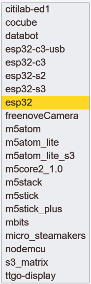
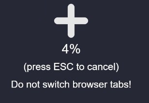
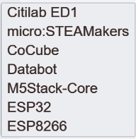
A VM selection menu of ESP boards is presented. After the selection is made, firmware update starts. A graphic display informs of the progress.
When the update is completed, you may be asked to reestablish the USB connectivity. See USB section.
erase flash and update firmware on ESP board
This command works only on boards with ESP8266 and ESP32 chips from Espressif. It erases the board's flash memory, including the file system and and any existing MicroBlocks program, then loads the latest firmware.
A device selection menu of ESP boards is presented. After the selection is made, firmware update starts. A graphic display informs of the progress.
When the update is completed, you may be asked to reestablish the USB connectivity. See USB section.
enable or disable BLE
Boards with BLE communications capability can use the BLE connection to facilitate editing the code wirelessly. However, in special cases, like using MicroBlocks in large group competiton settings, accessing the micro devices over BLE can be challenging, as well as against the rules of the event. This option provides control over this feature by enabling the user to turn off the BLE functionality.
This feature is located under the advanced settings menu, and will only be visible when the board is connected via an USB connection.
Setting of this option enables / disables the BLE advertising used by the micro device. As such, when the disabled setting is active, there will not be any BLE advertisings issued by the device. Hence, when the connect menu "connect BLE" option is used, one may not see any advertised BLE addresses, if there are no other BLE devices in the vicinity of the PC used for editing.
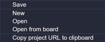
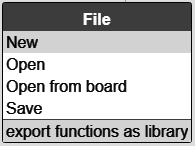
¶ File

File menu enables the user to handle saving and loading projects in various ways.
While the standard method involves writing a script and then saving it to the PC, MicroBlocks also supports retrieval of previously loaded scripts from the attached micro devices, as well as saving and loading scripts to/from URL designations.
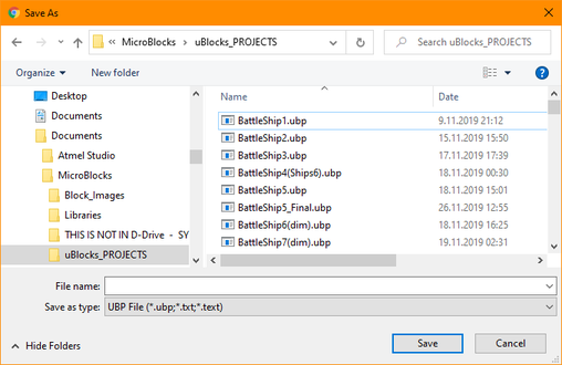
Save
This option opens an OS File dialog to select a file name and location on disk to save the program. The standard program extension is .UBP. If the program was previously saved, that location will be selected automatically and the filename will be set to the previously used name.
In cases where the program name matches an existing program name in the directory location, a message confirming the overwrite of the existing file will be displayed.
Save operation cannot be used to change the name of an already existing program on disk. If the program name is changed during the save operation, a NEW program copy with the new name will be created on disk. The only way to change the name of an existing program already saved to disk is to modify the existing name using the OS file functions.
New
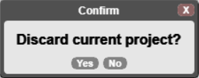
Used to start writing a new program. If there is a program loaded in the work area, it will display a message, asking for confirmation for clearing the active project.
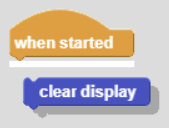
Upon positive confirmation, starts a clean new scripting area as shown below:
Scripting area is cleared of the previous script blocks. All user added libraries are cleared out. Depending on the micro device type and the setting of the option autoload board libraries, certain libraries may be loaded.
Open
This is how previously saved projects on user's PC are loaded into the work area. In addition to the user's own projects, other sample projects in various categories can be loaded.
If there is an active project already in the scripting area, a confirmation message is displayed. See File New above.
A file open dialog is presented:
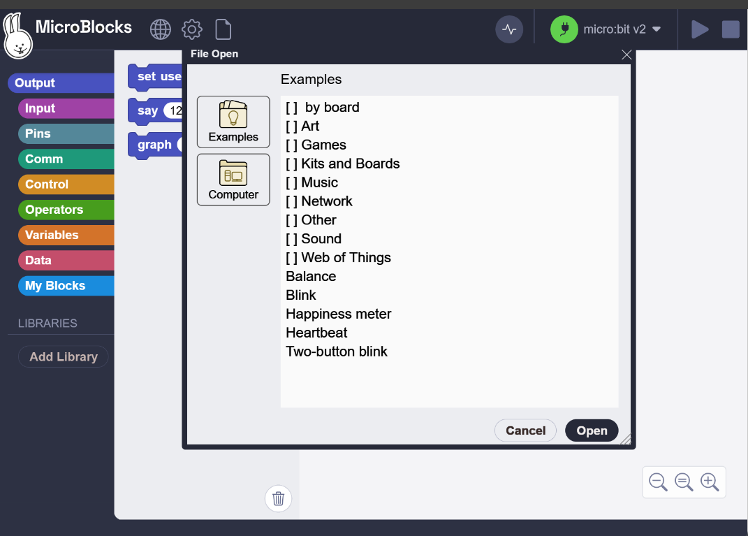
First display is focused on the Examples category, where many MicroBlocks projects for different micro devices and hardware options are presented.
User's own PC directories can be reached by switching to the Computer tab selection on the left. This will present the standard system file open dialog, where one can select previously saved projects.
Open from board
Another SUPER feature of the MicroBlocks editor is that it will load a project from the attached micro device, if there is no other project loaded into the editor. To ensure that the editor is free of any project blocks, select New from the File menu before using this feature.
If the connect icon is not green, then this option will be visible in the file menu. It will not be visible if the USB connectivity is established and the connect icon is green.
If there is an active project in the scripting area, a confirmation message is displayed. See File New above.
Assuming the above conditions are met, a message to connect the device is displayed:
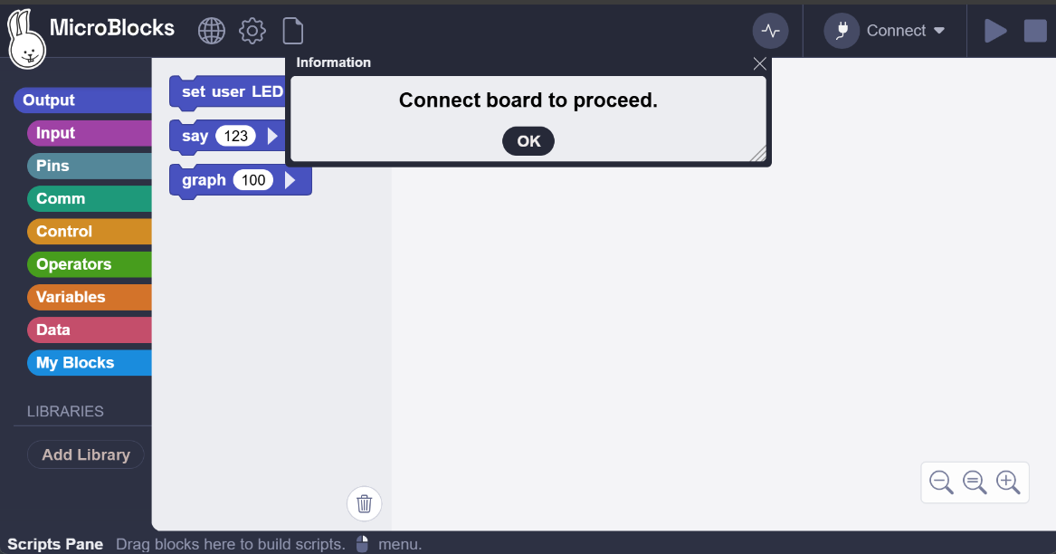
When the connection is established, MicroBlocks will read and load the project from the attached micro device.
Here is a progress display message from a micro:bit device, reading a project from board:
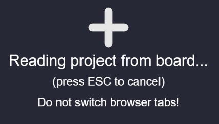
If the project is large, you may also see a message indicating the loading of the project.
Note that projects loaded in this fashion will:
- not contain project name and comments information that may have been in the original source version,
- not restore the blocks to their original locations on the IDE,
- not restore all libraries used in the original program if none of their blocks were used
The only way to preserve these info bits is to actually save the project file to one's PC at the time of creation.
¶ Alternative Program / Script Loading Options
In addition to the File Open command described above, there are several other ways of loading programs or individual scripts into the IDE.
- As URL:
When a program is copied to the clipboard as URL, the resulting link is copied to the Clipboard. This URL link can be used as a program reference in a document or on a web page. Clicking this URL link results in the MicroBlocks IDE to be executed with the referenced program loaded and ready to be edited or run.
Here is a link to the BLINK program in URL format.
When you click it, a MicroBlocks browser session with the Blink program loaded, will be started. You can then edit or run the program. Click and try it!
Be careful:
Whenever you work with projects saved as URL links, the link includes the type of MicroBlocks release (Stable or Pilot Release) information. When the link initiates a new MicroBlocks session and loads the project code, it will be in the same session type as it was saved. This may be different than what you were working with at the inception of the project. Since the Stable and Pilot Releases contain different feature sets, you may experience different functionalities.
- As a script fragment from clipboard:
Any and all of the individual scripts on the IDE can be saved to the clipboard via the R-Click menu options copy to clipboard, copy to clipboard as URL, copy all scripts to clipboard, and copy all scripts to clipboard as URL.
These fragments can then be PASTED into the IDE and worked on.
Here is a script fragment for the Blink script: Copy and paste it to the IDE.
GP Script script 454 51 { whenStarted '[display:mbDisplayOff]' forever { setUserLED true waitMillis 200 setUserLED false waitMillis 200 } }
- As a PNG formatted image file, incorporating the program or script:
PNG files support an embedded header option, into which the body of a program or an individual script can be placed. This is done by selecting R-Click menu options save picture of script or save picture of all visible scripts. The resulting PNG files can then be drag/dropped onto the IDE. This will load the embedded program, ready to be worked on.
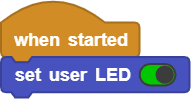
Here is a picture of the Blink Program that embeds the actual code. Drag it to the IDE.

NOTE: All of the options above will preserve any libraries used by the programs, and will restore them upon loading.
Programs embedded in PNG images:
Some image / multimedia handling software do not always preserve the internal formatting of the PNG files. These may drop or delete the embedded header sections containing the program code, resulting in unsuccessful restoral of the programs / scripts.
Save
Once a project is ready, it needs to be saved to the user's PC.
Selecting Save will display a system file dialog, where the user can give the program a name, assign a location, and save it to their PC.
There is no pre-configured file save location or option in MicroBlocks.
Designating the file locations on the PC is the user's responsibility.
Once a SAVE or LOAD location has been specified, it will be remembered
in the subsequent editing sessions.
¶ File Advanced
Copy project URL to clipboard
One of the ways to save or transfer the project to another editing / publishing environment is to export it as an URL.
When this option is selected, a copy of the project in the URL format is placed into the clipboard. Below is an example of the BLINK.UBP program saved as URL:
https://microblocks.fun/run/microblocks.html#project=projectName%20%27Blink%27%0A%0Amodule%20main%0Aauthor%20unknown%0Aversion%201%200%20%0Adescription%20%27%27%0A%0Ascript%2050%2050%20%7B%0AwhenStarted%0A%27%5Bdisplay%3AmbDisplayOff%5D%27%0Aforever%20%7B%0A%20%20setUserLED%20true%0A%20%20waitMillis%20200%0A%20%20setUserLED%20false%0A%20%20waitMillis%20200%0A%7D%0A%7D%0A%0A
The URL format can be broken down into several parts:
-
Protocol (https): This indicates that the connection to the website is secure and encrypted.
-
Domain (microblocks.fun): This is the address of the website that hosts the MicroBlocks application.
-
Path (/run/microblocks.html): This specifies the location of a specific file within the website. In this case, it points to the "run" directory and then to the "microblocks.html" file. This file contains the core functionality of the MicroBlocks online editor.
Different MicroBlocks IDE versions (Stable Release vs Pilot Releases) have different paths for the IDE. As such, when you save in either of these environments, the generated URL will point to the version from which the program was saved. -
Fragment (#project=projectName...): This part doesn't affect loading the page, but it provides additional information within the webpage itself. It's called a fragment or hash. Here's how it breaks down further:
- #: This symbol indicates the start of the fragment.
- project: This keyword tells the MicroBlocks program to focus on the "project" section.
- =projectName: This assigns a value (likely replaced with the actual project name) to the "project" section. Here the project name is BLINK.
-
Hidden Part: Encoded Project Data
The remaining text after #project=projectName is the encoded data related to the MicroBlocks project itself.
Saving projects in this way can result in extremely large URL strings, depending on the project's size and libraries used. At times, it may come in handy to use a URL-Shortener service. Here is the short version of the BLINK example used earlier, created via T.LY web service: https://t.ly/dtF9d (may not be permanent)
URL handling varies depending on the browser used. In addition, different document editing environments may place a limit on the URL strings used.
Maximum length of a URL in different browsers :
Most web browsers display the URL of a web page in the address bar. There is a limit on the length of the URL basing on the browser we use. Here are the details.
Google Chrome – Google Chrome allows the maximum length of the URL to be of the size 2MB (2,097,152 characters).
Mozilla Firefox – In Firefox the length of the URL can be unlimited but practically after 65,536 characters the location bar no longer displays the URL.
Edge – Edge allows the URL length to be a maximum of 2083 characters but not more than 2048 characters in the path portion of the URL.
Opera – Opera allows the URL length to be unlimited.
Safari – The maximum length of URL in Safari is 80000 characters after crossing this limit the page displays an error.
Apache(Server) – Apache allows the URL length to be a maximum of 4000 characters after which it throws an error message.
export functions as library
When custom blocks are created in a project, they normally will be saved as part of the user project file with an UBP extension.
If, however, it is desirable to make a library out of the custom blocks, and save and load them independently as library code (with an UBL extension), then they will need to be exported from the script and saved into a separate file.
This selection makes that happen.
It will display a dialog window, where the name of the library can be assigned and saved. The new file will have an UBL extension.

For further specific information on how to create a library, refer to the WIKI menu item: Creating A New Library.
¶ Project Name

Displays the name of the project in the scripting area.
The project name is usually assigned when a project is saved to a PC. Upon subsequent loading, this name will be shown here.
However, when projects are loaded onto a micro device, the project name, as well as some other info like comments, will not be included. Therefore, if open from Board feature is used later to import a project from an attached micro device, then the project name will not be known and not displayed here.
¶ Synch Indicator

As new programs are loaded to the IDE, or existing scripts are edited, this indicator shows the progress of synching to the attached microcontroller board. Normally, this is a very fast process and the icon is not visible. However, as new or additional scripts / libraries are loaded to the IDE or any of the existing blocks are edited, this indicator may appear and display the progress of synching the blocks to the attached microcontroller board.
Note that while this icon is visible, you will not be able to perform any editing in the IDE, until the activity is completed.
¶ Graph

Graph opens a graph window used by the graph block to plot data. (For details, see the Graph block description in the reference manual.)
¶ Connect

The Connect icon is used to display a menu that lists different connectivity options supported:
- connect - system USB ports that have micro devices attached to them,
- connect (BLE) - devices with BLE connectivity support,
- open Boardie - our new virtual device BOARDIE.
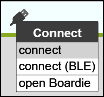
There is also the Open Boardie option for connecting to the virtual board Boardie.
As of the Pilot Release 1.2.52 VM 216 (Jan.2024), MicroBlocks started supporting programming activities via BLE (Bluetooth Low Energy) connection, thus enabling untethered programming (without the USB cable). This feature is supported on all boards that have the BLE communications implemented.
Refer to Bluetooth Details for more information.
¶ USB Connection Process
When connect (USB) is clicked, a system USB port menu is shown, with a listing of all USB attached devices on the PC.
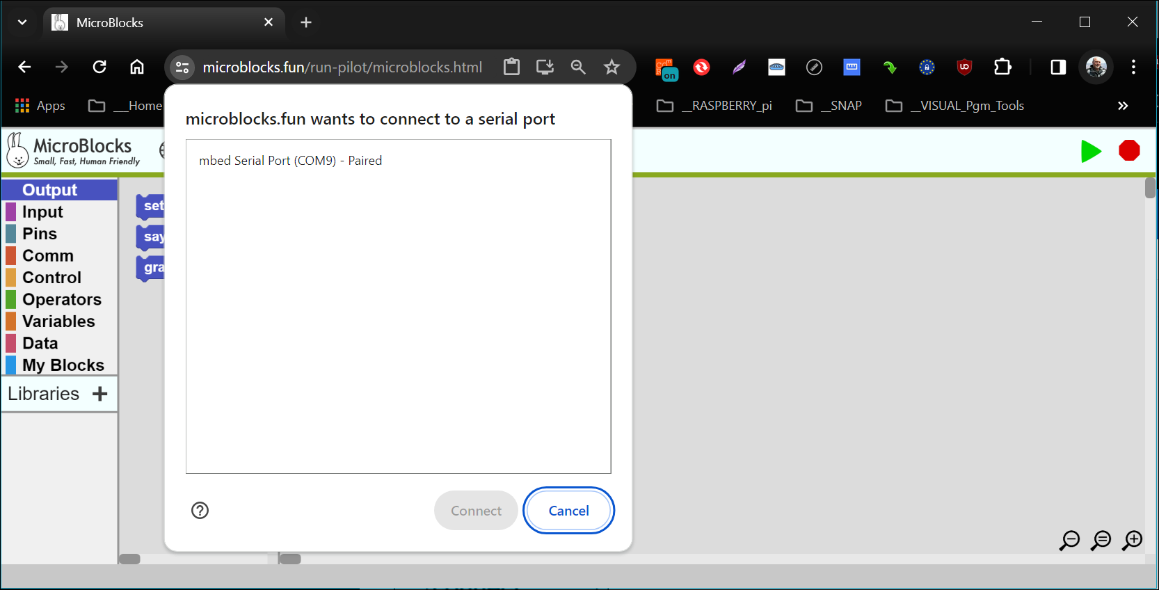
Selecting an entry and clicking Connect will establish a connection to the corresponding micro device.
¶ BLE Connection Process
When connect (BLE) is clicked, a system BLE port menu is shown, with a listing of all attached devices on the PC that have a BLE firmware loaded.
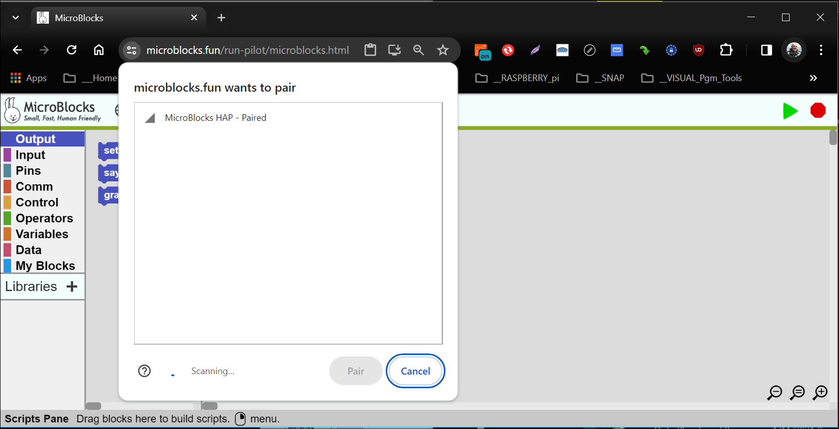
Note the three-letter code displayed with the MicroBlocks entry:
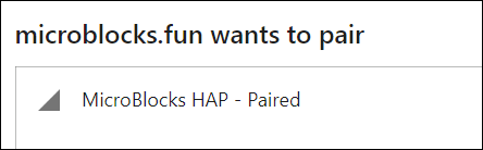
YZM - Paired indicates that a microcontroller with a BLE supported firmware was detected and annotated for the user. If there are more devices with similar capabilities, they all would be listed here with different three-letter codes assigned.
Note: Video below is from a device with a different BLE ID (HAP), as opposed to the one mentioned in the description above (YZM).
Adobe Video
The same three-letter codes are also displayed on the micro device LED display upon power up. This can be used to locate the correct device with which a BLE connection will be established.
Selecting an entry and clicking Pair will establish a BLE connection to the corresponding micro device.
¶ Connection Established
Upon successful connection, the USB icon will change to one with a green circular background:
![]() .
.
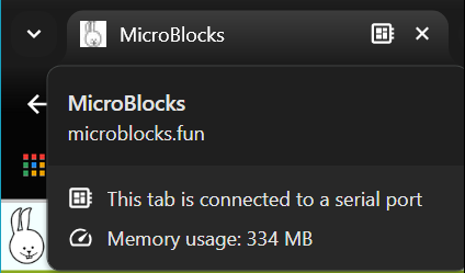
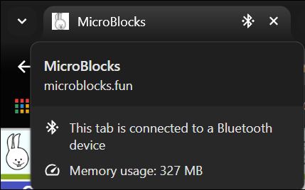
Another way you can confirm the connection status of MicroBlocks is by clicking on the browser tab for the MicroBlocks IDE. Depending on the USB or BLE connectivity established, you will see one of the two displays shown below:
It is important to pay attention to the status of this icon. MicroBlocks has a lot of internal automated processes to make the user's life easier when working in the editor. Automatic updating and synchronisation of the project code on the attached device is one of them. This is only possible when the icon is in green mode.
From time to time, for various reasons, the connection to the micro device might be severed. At these times the icon will not display the green circle. If you encounter this condition, editing of the programs should be paused and the reason for the disconnect should be investigated.
It is advisable not to develop or troubleshoot programs when the connection to the attached micro device is severed, indicated by the absence of the green circle around the USB icon.
¶ BLUETOOTH Connectivity Information
BLE Connection Support:
BLE connectivity support is a new feature of MicroBlocks, introduced as of Pilot Release 1.2.52 VM 216 (Jan.2024).
BLE connectivity enables one to work untethered to the PC where the MicroBlocks IDE is running. Normally, your microcontroller is connected to your PC via the USB cable, which provides the power necessary and enables programming activities provided by the IDE. This connection also necessitates that your microcontroller is located within cable-length of your PC.
When you connect via BLE, the idea is to jettison the USB cable connection and gain the ability to have the programmed device away from the PC. With bluetooth technology, this translates to a theoretical distance of 100m (300ft) or so. More likely, the practical distance without any obstacles will be somewhere around 25m (75ft). Nevertheless, that is quite far away from the PC used to program the microcontroller.
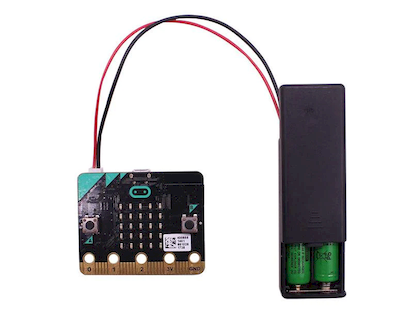
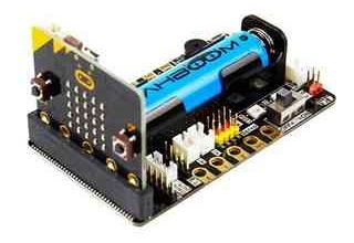
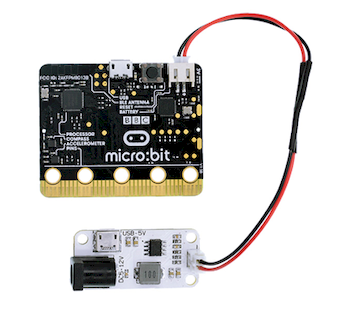
With the distance advantage gained comes a new problem: powering the microcontroller away from the PC. Without the USB cable, which provided power, one now has to use a different power source. This can be in form of a USB power-connection or a battery connected to the microcontroller. Many project kits also provide their own independent power source options.
We present several battery connectivity options below:
If you have never connected over BLE before, it is possible that your device's firmware does not have BLE support configured. Therefore, you need to update your firmware to the minimal release shown above. This firmware update has to happen over an USB Connection.
It is also possible that due to memory restrictions, BLE connectivity is not provided for your device. micro:bit v1 is such a case. You can still use the USB connection or upgrade to a more capable micro device.
Once you update your micro device to support BLE, all your future program updates can be done via BLE connection.
¶ Start / Stop Buttons

At the rightmost end of the main menu bar are the two icons Start and Stop, that are used to control the program execution.
¶ Start
MicroBlocks is always live; the user can click individual blocks or scripts to run them without clicking the Start button.
The main thing the Start button does is to simulate device power-on by starting all the scripts with when started and all the when <condition> scripts.
¶ Stop
STOP icon stops the execution of the project. All variables are deallocated. All scripts with when started and when <condition> are stopped.
The project loaded onto your micro device will be intact. In fact, you can disconnect it, power it on from an external source, and execute your project apart from the editor.
¶ Open Boardie
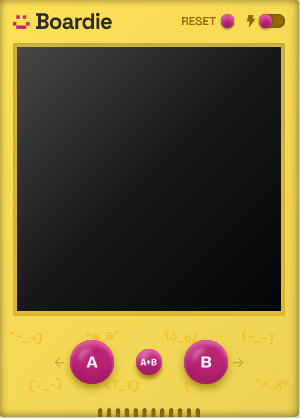
Boardie is MicroBlock's new virtual board feature. Now, even without a physical board attached to the computer, it is possible to explore programming with MicroBlocks by using Boardie.
Boardie emulates:
- a virtual board with a TFT screen of 240x240 size with 64K colors. By using the standard TFT and Turtle libraries, one can display text and graphics on Boardie.
- storage of 5MB using the browser LocalStorage feature, accessible via the Files library
- A, B, and A+B buttons
- Speaker, accessible via the Tone library
Functionality of Block Categories supported by Boardie:
| Block Category | Supported | Not Supported | ||
|---|---|---|---|---|
| Output | all | |||
| Input | all except: |
BLE id BLE connected |
||
| Pins | no | |||
| Comm | no | |||
| Control | all | |||
| Operators | all | |||
| Variables | all | |||
| Data | all | |||
| My Blocks | all | |||
| LIBRARIES | Tone Graphics and Displays / TFT Graphics and Displays / Turtle Other/Files |
Currently, Boardie is under development and its capabilities are changing all the time. We will document Boardie fully, when it is stabilized in a release.
¶ Working with Scripts
Since the scripting area is the most heavily used part of the editor, it is helpful to mention the operations and use conventions particular to this area.
One of the key points to keep in mind when working with scripts is the varying amounts of memory available in different microcontroller boards. To accomodate most boards we support, there is a limit on how big an individual script can get. This is set at approximately 1000 bytes. The amount used by any script can be verified with the block menu command show compiled bytes. Likewise, the entire program size can be verified using the MicroBlocks settings menu (Gear) option show program size on board.
¶ Block Operations
Blocks that are placed into the scripting area can be freely moved around with the mouse.
Additionally, there various operations one can perform on the blocks and scripts placed here.
¶ Keyboard Controls
Blocks can be manipulated by keyboard controls, as well as the mouse and the R-Click block menus.
Keybard shortcuts are used with the combinations of CONTROL and SHIFT keys:
-
CONTROL means duplicate
-
SHIFT means "extract or duplicate just one block"
(i.e. not all the blocks in the sequence below it) -
Drag (no modifiers) extracts the block and any blocks below it, as always
-
Control-drag is the same as "duplicate all"
-
Shift-drag is the same as "extract block"
-
Control-shift-drag is the same as "duplicate block"
¶ drag & drop
As mentioned above, drag and drop movement of the blocks is all too familiar to almost everyone who has spent some time with block based development environments (Scratch, SNAP!, MakeCode, etc).
What is different and very nice in Microblocks is that a block that is clicked on gets a nice drop shadow which highlights it against the background. This 3D effect makes it easy to perceive that the targetted block is in fact in motion, floating over the scripting area surface, even above other script blocks.
¶ block snap
As single or groups of blocks that are moved with the mouse, approach other blocks nearby, a horizontal yellow line will appear, designating a snapping point.
If one releases the mouse at that moment, the blocks under the mouse will snap to the blocks on the other side of the yellow line.
¶ Block Right-Click Menu
Right clicking any block within a group of blocks (script) will display a block level menu.

The contents of this menu will depend on the setting for advanced mode.
¶ duplicate
Selecting it will make a copy of the single block the mouse is positioned on.
Certain blocks (C-Blocks, IF-Blocks) may contain a bunch of other blocks within.
When duplicate is applied to one of these blocks, then the entire group will be duplicated.
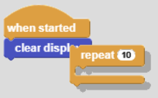
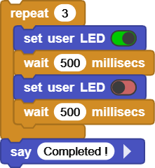
In the example below, the repeat C-Block is being duplicated, and the duplicate creates a complete copy of the repeat block and blocks within.
¶ duplicate all
This option is similar to the duplicate, with the difference being that, it duplicates all blocks below the selected one.
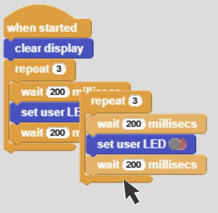
Based on the example we have been using, clicking on the repeat block and selecting duplicate all will duplicate the repeat block and all of the blocks under it.
Here again, the point to remember is that, if the "blocks below" are only within a C-Block, then duplicate all is constrained to the C-Block.
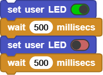
Second example shows what happens when the first block within the repeat block is clicked.
Only the blocks within the repeat block are duplicated, but not the enclosing repeat block.
¶ extract block
One of the pitfalls of block programming is that it is rather cumbersome to manipulate individual blocks that are in the middle of a group of blocks.
MicroBlocks is one of the few IDEs that handles this very gracefully, by providing a means to extract a block from a group of blocks.
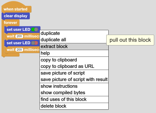
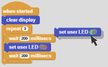
When clicked, the target block (or group of blocks) will be extracted and attached to the mouse pointer to be moved and placed somewhere else.
Note that the extraction process is not reversible or undoable. Try to remember the extraction point to be safe.
¶ help
Help block provides a link to the WIKI page that describes the target block. The web page opens up in a new tab and automatically positions itself to the block selected.
¶ copy to clipboard
This is a very handy operation that places a copy of the selected block sets to the clipboard.
These then can be pasted not only within the same project, but also between different projects.
It is even possible to copy/paste between different instances of the MicroBlocks editor (browser version or stand-alone version).
This operation has a related pair, copy all scripts to clipboard, that is accessed when the scripting area background is clicked. That one copies all the scripts in the project.
¶ copy to clipboard as URL
This is a feature that is mainly used to incorporate MicroBlocks programs into web page compositions, since the format is URL encoded. Here is an example of the program used above:
And this is the same program saved in URL format:
While this URL save sample is of a very small program (only two blocks) and the URL version is only about a line, an actual program will be of considerable larger size and the its URL version will also be of considerable length.
¶ save picture of script
This is another handy operation to make an image copy of the script or block selected. The image will be saved in PNG format and will contain the code of the script or block.
This operation has a related pair, save a picture of all scripts, that is accessed when the scripting area background is clicked. That one makes an image of all the scripts in the project.
The size of the saved image is controlled by the option set exported script size on the menu displayed when the IDE area is right-clicked.
Next step is where a system file dialog is displayed, and the user can designate the save location on their PC.
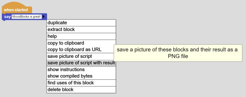
¶ save picture of script with result
You will see this operation only if the advanced blocks in the MicroBlocks (gear) menu is selected.
As with the other "save picture of script" option, this one makes an image copy of the script or block selected. However, before the picture is snapshot, the block / script content is executed and the result, if displayed, is included in the snapshot. Many of the examples provided in the Reference Manual are produced with this option.
Here are a sequence pictures demonstrating this operation.
A system file dialog is displayed, and the user can designate the save location on their PC.
NOTE: This operation waits till the first result is produced or the script execution is finished, before taking the snapshop. Therefore, it is NOT possible to take pictures of scripts where long or endless loops are active. Similarly, if there are multiple display points in the script, only the first one will be captured.
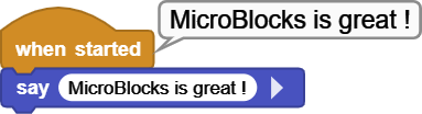
Check out this version of the example used so far.
Because there is a forever loop before the say display, the script never ends, the say message is never shown, and the save picture of script with result operation never gets to save the image.
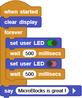
Now look at this version of the example:
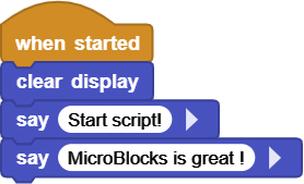
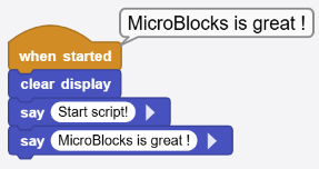
The image on the left is the script code. The image on the right is the execution result as seen on the IDE during the actual execution.
When this script runs, it will encounter the first say and display the "Start script!" result. This will cause the save option to intercept and immediately proceed to saving that combination. In the meantime, the script will continue execution and the second say block will display its message and overwrite the previous one. Since these happen very fast back to back, one will not notice the the first say result; but see the final say result as shown in the right picture. However, the second result display "MicroBlocks is great!" will never be captured to the saved image file.
REMEMBER: Both save operations described above work on the individual block level, as well as on a sequence of blocks, or entire scripts.
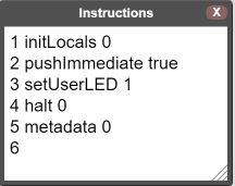
¶ show instructions
You will see this operation only if the show advanced blocks in the MicroBlocks menu is selected.
¶ show compiled bytes
You will see this operation only if the show advanced blocks in the MicroBlocks menu is selected.
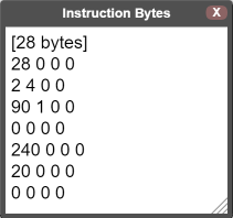
Most important part of this information is the first line, where the number of compiled bytes size is displayed. This information is important, because MicroBlocks scripts have a size limitation due to the limited micro controller memory sizes. Maximum compiled byte size for a script has to be no more than 1000 bytes.
¶ find uses of this block
This operation lists all occurrences of the selected block within the entire script, including custom blocks and libraries.
When items of the results list showing the occurrences is clicked, the specific program section containing the particular block will be shown and the block will blink a few times and then stop.
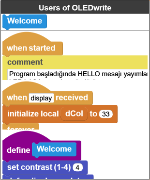
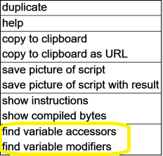
¶ find variable accessors
Two special versions of the "find" block are used in conjunction with the variables: accessors and modifiers. When a variable is right-clicked, the following menu is displayed with the find options.
This operation lists all occurrences of the variable block use within the entire script, including custom blocks and libraries.
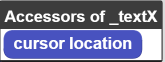
When items of the results list showing the occurrences is clicked, the specific program section containing the particular block will be shown and the block will blink a few times and then stop.
¶ find variable modifiers
This operation lists all occurrences of the variable block where the value is changed within the entire script, including custom blocks and libraries.
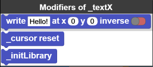
When items of the results list showing the occurrences is clicked, the specific program section containing the particular block will be shown and the block will blink a few times and then stop.
¶ show block definition
This block is used to display the contents of the custom blocks written by the users, and of any of the library blocks written in MicroBlocks. Some of the library blocks are implemented using code written at a lower level. These are not possible to display and when clicked on, will not display the option to show block definition.
¶ delete block
It deletes the target block or script. Blocks or scripts can also be deleted by simply dragging them onto the Blocks Palette area.
Be careful, currently DELETE is very final.
¶ Script Area Right-Click Menu
The final menu a user can encounter while working in the scripting area is the one displayed when the surface is right-clicked.
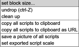
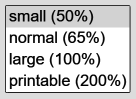
¶ set block size
When set block size is selected, a menu of block sizes will be displayed. Last blocksize selection used will be checkmarked.
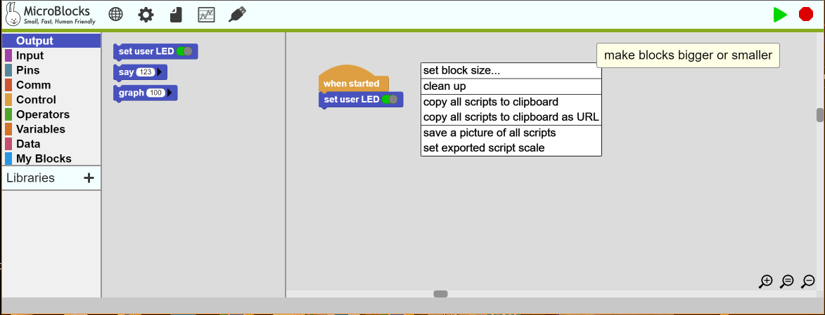
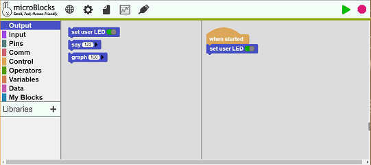
Block sizes will be adjusted based on the user selection made.
Here are results of the 100% and the 250% selections.
¶ undrop (ctrl-Z)
Reverses the very last block movement completed. Edits (copy, delete, and paste) do not count as movements. Movements are basically restricted to block location changes done with a clicked mouse.
As a matter of fact, if there were no block or script movements done when the script area was right-clicked, the undrop option is not displayed in the menu.
¶ clean up
Organizes the script segments and loose blocks on screen into a top down and left to right arrangement on the left side of the scripting area. Blocks are arranged in multiple columns determined by the width of the IDE area.
This operation cannot be undone !
¶ copy all scripts to clipboard
This is the complementary pair of the copy to clipboard operation. While the other one only copied the target block or script, this one copies all scipts in the project.
¶ copy all scripts to clipboard as URL
This is a feature that is mainly used to incorporate MicroBlocks programs into web page compositions, since the format is URL encoded. Here is an example of the program used above:
And this is the same program saved in URL format:
While this URL save sample is of a very small program (only two blocks) and the URL version is only about a line, an actual program will be of considerable larger size and the its URL version will also be of considerable length.
¶ save a picture of all scripts
This is the complementary version of the save picture of script operation. Instead of a single block or script, this one will make an image of all the VISIBLE scripts in the scripting area in PNG format. You can use the set block size command above to adjust block sizes, in case they do not fit the visible area.
Please note that if you have many scripts, it may not be possible to make all of them visible.
¶ set exported script scale
Controls the block size and resolutions of the saved scripts. The default is 200%.
In addition to the mouse and window scroll controls, keyboard arrow keys provide scrolling support while working in this area.
¶ Glossary
| Phrase | Definition |
|---|---|
| Custom Blocks | A set of scripts developed by the user to achieve specific functionality. It can also be referred to as a Custom Function. |
| Script | Single stack of blocks. |
| Library | Specific purpose scripts provided with MicroBlocks to handle various micro device features and functionalities, as well as to enhance standard capabilities of MicroBlocks. |
| Project | A combination of Scripts, Custom Blocks, and Libraries. |