¶ Pins
¶ read digital pin

Returns the value of the digital pin specified on the micro device as either true or false. A pullup true/false setting can be access by clicking the white triangle at the right end. Pullup setting forces the signal high in case of fluctuating voltages on the pin.
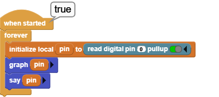
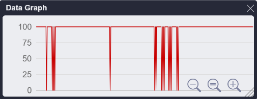
Digital pin 0 is read continuously and the results displayed and graphed. Pullup is enabled, meaning the normal status of the line is High.
read analog pin

Returns the value of the analog pin specified on the micro device as a number in range 0-1023. A pullup true/false setting can be access by clicking the white triangle at the right end. Pullup setting forces the signal high in case of fluctuating voltages on the pin.
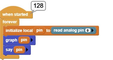
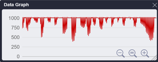
Analog pin 0 is read continously and the results displayed and graphed. Pin 0 is not connected to anything during the test. Pullup is NOT enabled, meaning the signal status of the line is fluctuating constantly, as can be seen in the graph.
set digital pin

Sets the state of the digital pin specified as either true or false. On a 3.3V device, a high setting will put 3.3V, and a low setting will put 0V on the pin.
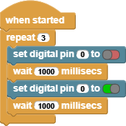
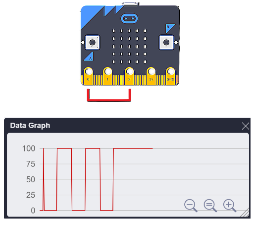
Two loops are coded. Left one toggles pin 0 three times between high and low settings. Since reading he pin status, while it is being changed, might affect its state, pin 0 is connected to pin 2 with a simple cable. In the right loop, pin 2 is read (should reflect the same values as pin 0) and graphed. The graph shows pin 0 toggling three times.
set pin (analog)

Generates a pulse width modulation (PWM) signal on the given pin that approximates a power level from 0-1023. PWM works by turning the pin on and off rapidly. The power is controlled by varying the duty cycle: the percent of the time during each cycle that the pin is on. A value of 0 means the pin is off, while a value 1023 means full power (i.e. the pin is on 100% of the time). A value of 512 results in a 50% duty cycle; the pin is on half the time and off half of the time. PWM can be used to control the brightness of an LED or the speed of a motor.
Some boards have one or two pins equipped with digital to analog converters (DACs). When this block is used with such pins, the pin outputs a steady voltage instead of a PWM signal. A value of zero means 0 volts, a value of 1023 means the full power supply voltage (3.3v or 5 volts), and 512 is half of the full voltage.
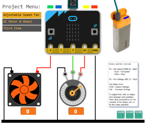
Program reads analog pin 2 in a continuous loop, and sets the analog pin 0 to the value read. This is a typical example of a motor controlled by a potentiometer, as shown in the picture.
Note: This simulation is simplified for the sake of clarity. Real motors require more power than the output pin of a microcontroller can supply. Thus, in practical motor applications the PWM signal from the microcontroller is connected to a transistor or motor control chip that drives the motor.
For video of the running example, see the video tab.
 |
 |
|---|
analog pins

Returns the number of analog pins present in the connected micro device.
Program displays the attached device's type and the type and number of pins it supports.

digital pins

Returns the number of digital pins present in the connected micro device.
See analog pins example above.


