¶ Comm
Advanced
The Comm category contains blocks that communicate with hardware devices over an Inter-Integrated Circuit (I2C, pronounced "eye squared sea") or Serial Peripheral Interface (SPI) bus. These advanced blocks are usually used by people with hardware experience to create libraries for devices such as sensors or the Hummingbird:bit robotics kit.
To use these blocks, you'll need to study the data sheet for the hardware device of interest. Many I2C and SPI devices must be configured or enabled before use. It is often helpful to find and study the source code of an existing library for the device.
NOTE:
MicroBlocks variables have a max string size of approximately 1000 bytes. Therefore, any comms operations utilizing buffers for comms data need to be cognizant of this limit.
Also, there is a suggested I2C buffer size limit of 32 bytes. This will ensure that exchanges with other devices are completed without buffer overflows.
On a few processors that support it, including the Pi Pico, one can use the set i2c pins system block to change the I2C pins under program control. That block is in the "Other/System/sensorPrims" library.
This is an experts-only block because
a - the ability to switch I2C pins is only available on certain processors (e.g. Pi Pico and ESP32); so using this block results in code that is not portable across boards and
b - with the Pico, you can only switch to certain pins. In particular, you can only use pins on the same I2C controller as the original pins, which is I2C0 on the Pico and Pico-W.So, based on the RP2040 pinout:
SDA can be: 4, 8, 12, or 16
SCL can be: 5, 9, 13, or 17This feature is not often used and not guaranteed how well it will work to use it to simulate an I2C multiplexer.
¶ i2c get register

Return the value of the given register (0-255) of the given I2C device (0-127). Check the data sheet for the I2C device for the device address and register assignments.
If successful, this block returns a positive 8-bit value (0-255). A negative return value indicates an error such as the I2C not responding.
¶ i2c set register

Writes an 8-bit byte (0-255) to the given I2C device and register.
¶ i2c read list

Receives multiple bytes from the given I2C device. The caller provides a list or byte array whose length is the number of bytes to be read. If successful, this operation replaces the items of that list or byte array with the bytes read from the device.
I2C read operations need to specify a device register address where the read is expected to start. This is usually accomplished by first executing an I2C write operation, where the written value is the address of the desired read register address. This will set the read pointer to the given address. Subsequent reads will keep on reading starting at that address and increment automatically, until enough bytes have been read to fill the provided list. However, not all I2C devices support auto-incrementing the address so check the device datasheet.
Note: I2C hardware buffer sizes vary. To maximize portability, it is best to read no more than 32 bytes at a time.
¶ i2c write list

Sends multiple bytes to the I2C device specified. The list should contain integers in the the range 0-255.
You can also send a byte array or string with this block. Note that strings UTF-8 encoded so any characters outside of the 7-bit ASCII will be sent as multi-byte sequences.
As in the I2C read operation, the write operation also needs to specify a destination register address, where writing will start. Therefore, the first byte of the write operation is usually the destination register address. This is followed by the actual data bytes that will be stored at the designated register address and incremented sequentially, until the providd list is all written out.
Note: I2C hardware buffer sizes vary. To maximize portability, it is best to write no more than 32 bytes at a time.
¶ spi send

Sends a byte (0-255) to the SPI device.
SPI hardware transmits and receives data simultaneously. On each clock pulse, a bit is read from the SPI input line while a bit is output on the SPI output line. This block discards the byte received from the SPI bus as the byte is sent.
¶ spi receive

Reads a byte from the SPI device while sending a zero byte and returns the received byte.
¶ serial open

Opens the Serial port at the specified baud rate. This necessary before one starts using the serial port communication.
Depending on the micro device used, serial ports are located on different pins of the device. Please refer to the WIKI Special Pins section for the device specific pin number information.
Serial Port support is NOT available for micro:bit v1 devices due to lacking hardware support. However, there is a "soft serial write" block designated for these limited environments. Note that it is transmit only over any available digital pin !
| TinkerCad Video |
 |
|---|
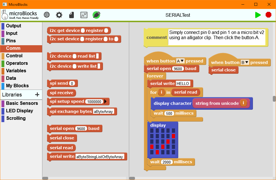
This example enables you to experience the Serial Port block set in the easiest way possible. The sample program uses all of the Serial Port blocks.
Simply connect pins 0 and 1 of your micro:bit v2 device with an alligator cable, creating a loopback circuit.
This will make the sample program transmit the string "HELLO" on pin 1 and receive it on pin 0 continuosly, when button-A is pressed.
When you are done, you can press button-B and close the Serial Port.
NOTE: The 500ms delay inserted into the read/display loop of the sample code is only there to make the displayed letters all visible.
The read serial block will function without any delays.
¶ serial close

Closes and terminates the serial port communications.
¶ serial read

Returns a byte array of data read from the serial port. In cases where these might represent character unicode values, they need to be converted using the string from unicode block into actual letters. An alternate way to convert the serial buffer to string is by using the join block, where the first slot is empty and the second slot is the serial buffer variable.

Below is an example of string "HELLO" read extracted from the sample program above. What you see is the decimal character codes of the letters:
H: 72
E: 69
L: 76
L: 76
O: 79

Assuming that the serial buffer read contains the word HELLO (72,69,76,76,79), we can convert the buffer to string representation via the join block:

Byte Arrays contain byte values of 0 - 255.
¶ serial write

Writes a byte, a string, or a byte array to the serial port. The data to be written must be 128 bytes are less. Larger amounts of data can be written with the serial write reporter block.
In case you would want to write a byte array to the serial port, you can easily create one with the newly added block as byte array under the Data category of blocks.
Here is a picture of what that block outputs:

¶ serial write starting at

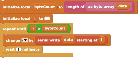
Write a byte array to the serial port starting at the given byte offset and return the number of bytes written. Using this block, a MicroBlocks loop can efficiently write a long byte array to the serial port.

¶ soft serial write

Writes a byte to the designated soft serial port. Used with devices that lack a dedicated UART chip, eg: micro:bit v1.
This block gives one the flexibility to output to any digital pin on the microcontroller.
Maximum baud rate is 115200.
Note that the pin used for this block needs to be connected to the RECEIVE pin of the other microcontroller, and the other microcontroller needs to be configured with the same baud rate.
¶ duelink receive

Returns a byte array of data read from the DUELink device.
¶ duelink send

Write a byte array to the DUELink device starting at the given byte offset and return the number of bytes written. Using this block, a MicroBlocks loop can efficiently write a long byte array to the device.


