¶ Overview
This project demonstrates how a SNAP program can be used to prepare an image to be transferred and displayed on a 0.96in or 2.42in monochrome OLED display attached to a micro:bit v2. These displays support a resolution of 128x64 pixels and require the image data to be formatted a specific way. The SNAP program used here handles this image transformation.
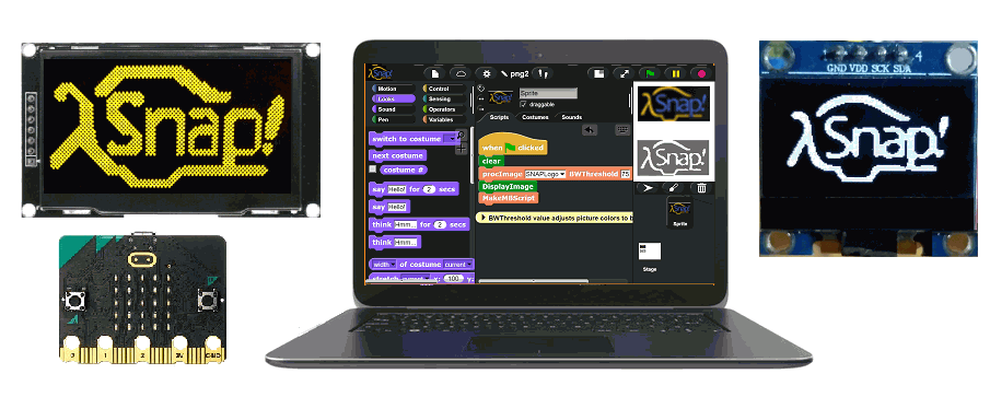
The SNAP program generates the MicroBlocks code and data required to handle the image in MicroBlocks. The code generated is transferred to the MicroBlocks environment via the system clipboard.
The MicroBlocks project uses the OLED128x64(1306-09) library to control the display hardware. The library is a hardware driver written entirely in MicroBlocks. It provides a functionality similar to the C++ libraries written by Adafruit and others to drive similar displays from an Arduino and other microcontrollers.
NOTE: This project will only run on the micro:bit v2 or other board with enough memory for the display buffer; it does not run on a micro:bit v1.
¶ Parts
You will need the following parts:
- micro:bit v2
- USB Cable to connect the micro:bit to laptop
- 128x64 pixel OLED display (w/ 1306 or 1309 controller chip)
- Edge Expander board
- Four to seven jumper wires, depending on the connection type selected
Two display types can be used in this project:
- 0.96in OLED 128x64 display (I2C only)
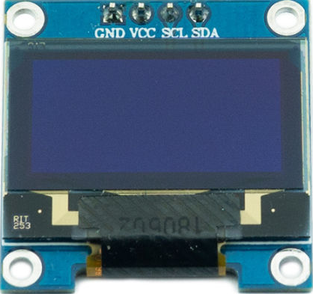
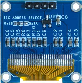
- 2.42in OLED 128x64 display (SPI or I2C)
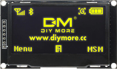
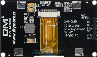
Some displays can be configured for either I2C and SPI connectivity, others support only I2C. I2C requires fewer connections and shares the I2C pins with other I2C devices, but SPI is faster.
NOTE: The displays that work with either I2C or SPI come configured for SPI by default. They require a hardware modification to use I2C connectivity. Users not comfortable making those hardware modifications can stick with SPI.
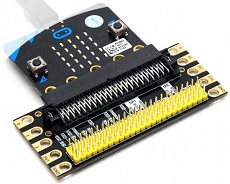
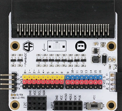
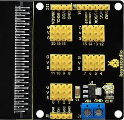
You'll need an Edge Expander board to connect to the micro:bit's I2C or SPI pins. Here are some examples:
¶ Connecting the Display to micro:bit
The first thing that must be done is to connect the display to the micro:bit v2 using the Edge Expander boards. These boards have both the I2C and the SPI pins already separated and labeled (examples are shown below).
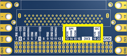
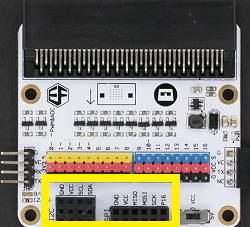
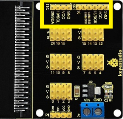
Since there are two different connectivity types (I2C and SPI), we will describe how to connect each one separately.
¶ I2C Connections
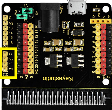
The micro:bit uses pins 19 and 20 for the I2C bus. The display also needs to be connected to power and ground. For example, on the Keyestudio Edge Expander, the pins are labeled:
| G - Ground V2 - 3.3V P19 - Clock (SCK or SCL) P20 - Data (SDA) |
 |
|---|
NOTE: Different Edge Expander boards label their pins differently:
Ground Pin may be labeled as G, GND; and
Voltage Pin may be labeled as V, V1, V2, Vcc, 3.3V, 5V.
Some Edge Expanders support both 5V and 3.3V. These displays can operate on either voltage, but 3.3V is preferred.
¶ Connections for an I2C only display
An I2C only display (4-pin connector), has these pins:

Make the following connections:
| Edge Expander | OLED Display |
|---|---|
| G | GND |
| V2 | Vcc |
| PIN-19 | SCL |
| PIN-20 | SDA |
NOTE: You need to obtain FOUR jumper cables of suitable size to reach from the Edge Expander board to the pins on the Display. They also need to be of the correct type (male/female) to provide connectivity between the devices.
¶ I2C connections for a combined I2C and SPI display (uncommon)
Displays that support both connectivity types can be identified by a 7-pin connector. The pins will be labeled:
 |
CS - Chip Select DC - Data/Command RES - Reset SDA - Data SCL - Clock Vcc - 3.3V GND - Ground |
|---|
Displays that come with this type of connector are configured to operate in SPI mode by default. They can optionally be controlled using I2C instead by making some a hardware modifications (moving a surface-mount resistor). That process is described in the display hardware documentation.
If you've modified your display to use I2C, make the following connections:
| Edge Expander I2C |
OLED Display I2C |
|---|---|
| not used | CS |
| not used | DC |
| PIN-8 * | RES |
| PIN-20 | SDA |
| PIN-19 | SCL |
| V2 | VCC |
| G | GND |
While I2C itself uses only 4 wires, displays with 7-pin connectors require an additional connection to the RESET pin of the display to perform a hardware reset of the display.
NOTE: Here, PIN-8 is used as the RESET pin, but any available micro:bit pin can be used instead by changing the reset pin parameter in OLED display initialization command.
¶ SPI Connection
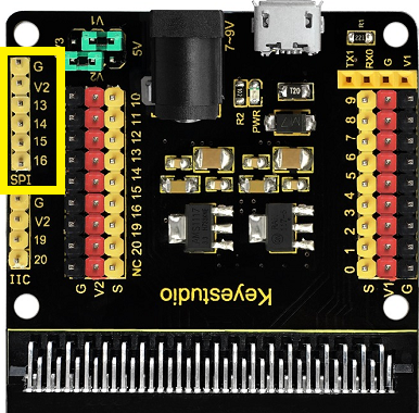
The micro:bit uses pins 13, 14, and 15 for the SPI bus. On the Keyestudio Edge Expander, for example, the SPI pins are labeled:
| G - Ground V2 - 3.3V P13 - Clock (SCK or SCL) P14 - MISO (not used) P15 - MOSI P16 - not used |
 |
|---|
NOTE: Different Edge Expander boards label their pins differently:
Ground Pin may be labeled as G, GND; and
Voltage Pin may be labeled as V, V1, V2, Vcc, 3.3V, 5V.
Some Edge Expanders support both 5V and 3.3V. These displays can operate on either voltage, but 3.3V is preferred.
Displays that support both I2C and SPI connectivity types can be identified by a 7-pin connector. Displays that come with this type of connector are configured to operate in SPI mode by default. The pins will be labeled:
 |
CS - Chip Select DC - Data/Command RES - Reset SDA - Data SCL - Clock Vcc - 3.3V GND - Ground |
|---|
Make the following connections:
| Edge Expander SPI |
OLED Display SPI |
|---|---|
| G | CS |
| PIN-16 | DC |
| PIN-8 * | RES |
| PIN-15 | SDA |
| PIN-13 | SCL |
| V (3.3) | VCC |
| G | GND |
NOTE: Here, PIN-8 is used as the RESET pin, but any available micro:bit pin can be used instead by changing the reset pin parameter in OLED display initialization command.
Standard SPI uses 3 wires to perform a bi-directional data exchange: Clock, MISO(Master-In Slave-Out), MOSI(Master-Out Slave-In). Since this OLED display is an input-only device, the MISO pin is not used. However, the display uses the Data/Control (DC) pin to distinguish between command and data bytes and the RESET pin to perform a hardware reset. Since this project uses only one SPI device, the Chip Select (CS) pin is simply grounded (i.e. the display is always selected).
¶ Scripts
This project consists of two programs, one written in SNAP and one written in MicroBlocks.
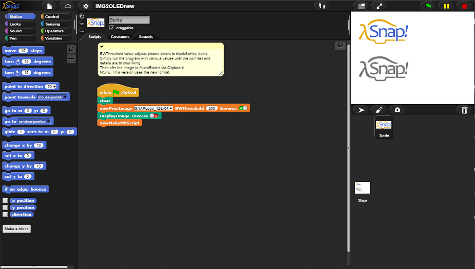
The SNAP program (img2oled.xml) transforms an image into a format suitable for displaying it on the OLED display and generates a set of MicroBlocks scripts that encode the image data.
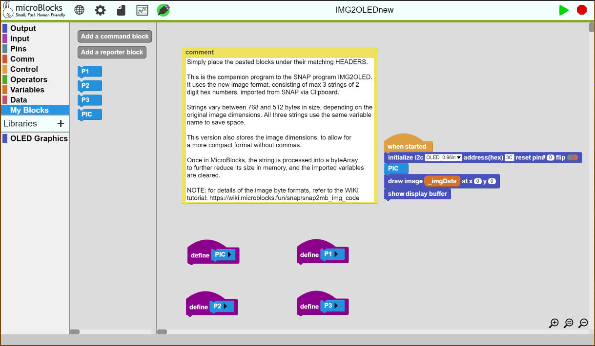
The MicroBlocks program (img2oled.ubp) provides access to the OLED128x64(1306-09) Library and displays the image on the attached OLED display.
¶ Running the SNAP Program
The SNAP program comes preloaded with a few example sprite costumes. These provide a good starting selection of various image types: color, black&white, pre-sampled to pixels, and patterns. You can easily add your own images, by observing a few simple rules:
- Images must be loaded in the same orientation as they will be shown on the display.
- Images must be no larger than 128x64 pixels in size. They can be smaller.
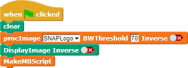
The script performs three tasks:
-
#1: It processes the user selected image.
The image selection is done via the first dropdown menu, which displays the names of all the loaded sprites. At the end of the process, image is converted to a suitable format for showing it on the OLED displays. Two options, BWThreshold and Inverse provide a level of simple image manipulation, depending on the type of result one wishes to achieve.
BWThreshold - controls the color to black&white conversion level, while also affecting the level of detail one gets to see in the processed version.
Inverse - simply inverts the bits to display a reverse video of the original image. This is handy for images that might have a solid color backgrounds that one might want to eliminate. -
#2: It displays the original and the processed images.
It displays a stamped version of the sprite on the top of the screen so one can see the original version. And it also prints the processed bits, so one can get an idea of what the OLED version of the image is going to look like.
As in the previous step. one has the control to inverse the image. This only changes the SNAP display version, not the processed version. -
#3: It generates the MicroBlocks code blocks to format and transform the images.
Since there is no local storage in the micro:bit, we are using a technique of embedding the image data in a program variable, and then transferring the combined data and code to the micro:bit. The image data and the program codes to manipulate it are placed in the Windows Clipboard buffer. This allows the user the ultimate simplicity to edit the MicroBlocks program to complete the task at hand.
After clicking the Green Flag, the display will show two images and the program will terminate. One can run the SNAP program as many times as desired, selecting different sprites or adjusting the selection for various BWThreshold values.
After each run, your MicroBlocks code is copied to the clipboard, ready to be pasted into the MicroBlocks IDE.
¶ Running the MicroBlocks Program
The MicroBlocks program uses the OLED128x64(1306-09) Library to control the attached display hardware. Based on the two display connectivity types supported (I2C and SPI), there can be two different display initialization sequences:


The script performs three simple tasks:
-
#1: It initializes the the OLED display according to the connection details selected.
Depending on the display type, set the display selection in the first dropdown field.
For I2C displays, the I2C Address and the RESET Pin values have to be provided.
For SPI displays, the D/C Pin and RESET Pin values have to be provided. -
#2: It processes the images based on the code that was exported from the SNAP program.
The PIC block is one of the codeblocks that is pasted into the IDE from the Clipboard. It processes the parts of the image data, creating the required structures to print it on the OLED display. -
#3: It draws the image on the OLED display.
The draw image block places the image data to the virtual display buffer in the Library, and then displays it.
Virtual display buffer provides many opportunities to enhance the GDBuffer data using the library blocks. One can add text, draw frames around the image etc. Once the final composition is done, then the entire buffer can be sent to the display. The same technique can be used to program simple games and animation.
When the program is first loaded to the IDE, it comes ready to receive the data and codeblock from the SNAP companion program.

First thing to do is to verify and change the initialize block under the when started block. Depending on your display hardware and connection type, select either I2C or SPI versions, and then set the specific address, size and pin info in the block.
There are four define Header blocks, PIC and P1-P3, without any code under them. Code blocks pasted from the clipboard will need to be placed under the corresponding headers. Place the mouse pointer somewhere below those blocks and then Right-Click the mouse and select paste all scripts from clipboard.
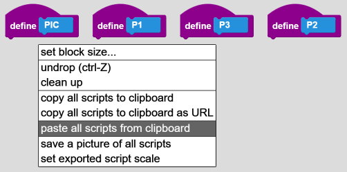
Subsequently, all image and code blocks in the clipboard will be transferred into the IDE coding area. Since the size is rather large, we can only show a part of the IDE in the picture below.
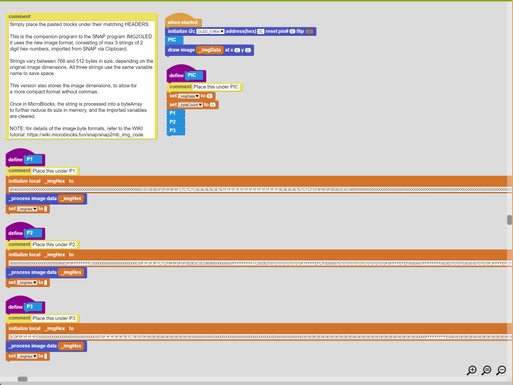
What one sees is anywhere from two to four block sets pasted onto the IDE. Each blockset is preceeded by a comment that directs the user to properly place it under to corresponding Header block.
Once P1 - P3 blockset have been matched to their headers, the last one, the PIC block, has to be placed under the PIC header block. This will complete the program modifications and make it ready to process and display the image transferred from SNAP.
All that is left to do is to click on the RUN icon and get the image onto the OLED display.
Below is the SNAP starting point and the MicroBlocks ending point of this project.
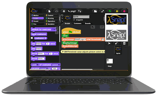
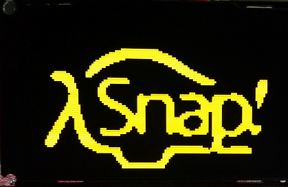
We hope you will explore and experiment with your images and Library features.
¶ Project Download
SNAP Program: IMG2OLEDnew.xml
If you are having problems downloading the SNAP program, try R-Click on the link and select Save link as option.
MicroBlocks Program: IMG2OLEDnew.ubp - use this program to place images on the OLED displays.
OLED Library Demo Program - this program demonstrates the library blocks and provides examples on how to use them.
¶ Notes on the Image Processing for the OLED Displays
As explained in the datasheets linked above, the SD1306/1309 displays have some interesting characteristics. First, they can organize the image data in two different scan orientations: Horizontal or Vertical.
HORIZONTAL:
In this mode, image bytes are sent to the display starting at top left origin 0,0 in Left-to-Right manner.

LSB of each image byte is at the top and MSB is at the bottom of the respective columns. When column 127 is reached, the display hardware will wrap to the beginning of the next row (page) and continue.
This is the mode used by the MicroBlocks virtual display buffer.
VERTICAL:
In this mode, image bytes are sent to the display starting at 0,0 in Top-to-Bottom manner.

LSB of each image byte is at the top and MSB is at the bottom of the respective columns. When row (page) 7 is reached, the display hardware will wrap to the beginning of the next column and continue.
GDDRAM Layout
It is important to keep in mind that image data sent to the display is in units of BYTES, and not pixels. Therefore, every byte occupies a vertical of 8 bits in each display position. This makes the 64 pixel vertical dimension become separated into 8 pages (rows) of 8 pixels each, spread across 128 columns; giving us the 8 x 128 = 1024 display bytes.
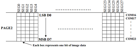
This design also imposes the restriction that image data bytes are constrained to row boundaries.
Virtual Display Buffer
Another interesting design decision by the display manufacturers is the fact that in the Serial (SPI and I2C) communication mode, they have disabled the ability to read the hardware display buffers. This creates a condition where the internal buffer data is unknown, successive writes to the display are destructive, and there is no way to create composite images by overlapping image data.
We have overcome this problem in MicroBlocks by defining a 1024 byte virtual display buffer and redirecting the image data to this buffer. Since the display buffer is under user program control, any design can be overlayed on it and when done, the composite image can be displayed. This way, if one wants to create complex images (e.g. some text with a rounded rectangle around it), the virtual buffer can be used.
There is but one complication with this implementation: the virtual display buffer is a LIST of 1024 bytes organized in the horizontal layout. Therefore, images must use the horizontal mode of the display.
SNAP Program - IMG2OLED:
As can be seen from the above description, image data layout for the OLED displays can be quite complex and confusing. Fortunately, you don't need to worry about those low-level details. The SNAP program automates the process of preparing images for display. You just need to import your image into SNAP as a costume -- in the size and orientation it will be shown on the display -- and the SNAP program will process it and generate MicroBlocks scripts containing the image data.
To make image import easy, the source image is just a SPRITE costume. You can drop an image in any supported image format onto the SNAP window and it will be imported as a SPRITE costume.
It is up to the user to place the source images in the desired orientation and to ensure that their dimensions are no more than 128x64.
There are controls in the SNAP program to handle the color to black&white conversion, as well as the inverse video for certain backgrounds. One can play with these setting and keep running the SNAP program, until an acceptable rendition is achieved. Please note that this programm is NOT a sophisticated image editing software, and it can only do limited adjustments. If the program results are not to your liking, you are advised to use an outside image editing software to process your image, and then import it to SNAP.