Libraries are collections of blocks that enhance MicroBlocks with additional functionality and allow MicroBlocks to interface to a wide variety of external hardware devices.
MicroBlocks comes bundled with dozens of libraries, but users can also develop their own libraries. To learn how, see Creating A New Library.
¶ Importing Libraries
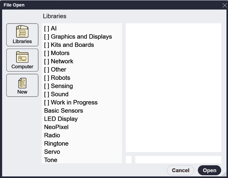
The picture above shows the library import dialog that appears when the Libraries + button is clicked. This dialog lists all the libraries that come bundled with the MicroBlocks IDE.
The entries starting with [ ] are folders for various library categories. These folders contain dozens of libraries, most of them connected with specific of hardware and many of them contributed by the MicroBlocks community. Some of those libraries will be described in separate sections below.
There are also some individual library listed below the folders. Those frequently used libraries are described below.
Many libraries use features that are not available on all boards or require external hardware devices. For example, the Radio library works only on boards with a Nordic nRF5x processor, while the Servo library requires an external servo motor. When using a library, make sure you have the required feature or hardware.
Libraries can be loaded regardless of the actual hardware. That allows you to write code for a devices that are not currently connected. Some blocks will display error messages if they are run without the necessary hardware, others will simply have no visible effect.
TIP:
If you are developing libraries and have a need to load them for dev and testing, you can simply drag and drop your personal UBL files onto the IDE, and they will be listed in the Libraries menu.
¶ Frequently Used Libraries
This section describes the most frequently used libraries. These libraries enable users to access and control sensors and hardware features found built into the most popular microcontrollers. For example, here are the hardware features of the micro:bit v2:
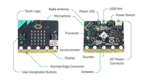
Many boards have accelerometer chip that provides 3-axis sensing of acceleration/gravity and a sensor that provides an estimate of ambient temperature. Some boards also have a light sensor or a magnetic field sensor.
The Basic Sensors library provides access to those built-in sensors when available.
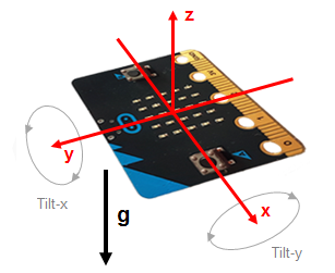
¶ tilt x y z
   |
 |
|---|
These three blocks report the tilt values in three axes. The normal value range is -100 to +100 but values can reach -200 to 200 when shaken. (100 means 1 G of acceleration.)
¶ acceleration

Acceleration is the total acceration (or "G force") experienced by the device regardless of the direction. It is always positive, with a range of 0-346.
¶ light level

The light level has a range of 0 - 1023. Light sensors vary in sensitivity, even among boards of the same type (e.g. micro:bits), so you'll need to experiment to discover the working range of your board's light sensor.
¶ temperature

Temperature is reported in degrees Celsius. The range of the temperature sensor varies across boards but it is usually at least 0 to 50 °C. These built-in temperature sensors are not calibrated and often vary between boards. Check your board against a trusted thermometer to figure out how to many degrees to add or subtract to get the actual temperature. Once calibrated, many built-in temperature sensors are accurate with one or two degrees Celcius.
¶ magnetic field

Reports the magnetic field strength on microcontrollers with a magnetic field sensor, or zero on other boards.
On microcontrollers with an accelerometer chip, the range is roughly 0-100000 and the sensor is sensitive engough to detect the Earth's magnetic field or the magnetic field from the electrical current flowing in a wire, if the wire is very near the chip.
The ESP32 Hall Effect sensor is not as senstive. It has a range of 0-1023 and can detect when a magnet (e.g. a strong refridgerator magnet) is nearby.
¶ set acceleration range
This is an advanced block

By default, the full range of the accelerometer is +/- 200, with 100 being one G. One G, the acceleration of gravity on Earth, is the acceleration that a microcontroller experiences when it sits motionless on a table.
The default range is great for measuring tilt or detecting gentle shakes. But it can also be interesting to measure higher accelerations, such as the rapid deceleration? that occurs when objects collide. This advanced block allows the maximum acceleration range to be changed to measure such higher accelerations.
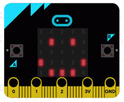
The display is a 5x5 array of LEDs. It is connected to the micro:bit as a 5x5 matrix. Runtime software repeatedly refreshes this matrix at a high speed, such that it is within the user persistence of vision range, and no flicker is detected.
This LED matrix is also used to sense ambient light, by repeatedly switching some of the LED drive pins into inputs and sampling the voltage decay time, which is roughly proportional to ambient light levels.
The 5x5 LED matrix size can only display one character at a time. To display words or numbers, the scroll test block is handy. It has the ability to slide text and numbers across the screen with varying speeds that the user can control.
¶ display
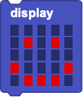
The display block allows the user to create different shapes and patterns for display on the 5x5 LED matrix. Click on one of the small rectangles to turn it on or off. Click and drag to change multiple rectangles.
To drag the block itself, pick it up by the top portion of the the block, where the word display appears.
¶ display image

Displays one of the selected icon images on the LED display.
¶ clear display
![]()
Clear the display; all LEDs are turned off.
¶ plot x y

Individual LEDs can be turned on using this block.
X specifies the column (1-5), from left to right.
Y specifies the row (1-5), from top to bottom.
For example, x=3 and y=3 is the LED in the center of the matrix while x=1 and y=1 is the top-left LED.
¶ unplot x y

Individual LEDs can be turned off using this block, using the same x and y coordinates as plot x y.
¶ display character

Displays a single character on the LED display. Only the printable ASCII characters can be displayed.
¶ scroll text

Scroll words or numbers from right to left on the LED display.
The optional pausing parameter controls the scrolling speed. Bigger numbers result in slower scrolling.
¶ stop scrolling

Stops scrolling text and clears the display.
¶ set display color

Sets the color of the 5x5 square LED pixels to the color selected.
This is only effective on TFT displays with multiple color support.
¶ led image
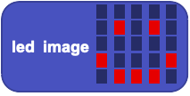
Reports a number representative of the image drawn on the 5x5 LED panel pixels.
This number can be used to draw the image using the display image block. Either this block itself or the number it produces can be used as input to the display image block.
¶ _led_namedImage

Returns the integer value representing the image selected from the drop-down menu.
This number can be used to draw the image using the display image block. Either this block itself or the number it produces can be used as input to the display image block.
Adafruit Video
NeoPixels are small LED modules that combine red, green, and blue LEDs with a tiny controller chip. Neopixels can be individually controlled by a microcontroller create different colors and patterns. A single microcontroller pin can control dozens -- or even hundreds -- of NeoPixels. NeoPixels come in many configurations including rings, bars, grids, and flexible strips.
¶ attach NeoPixel LED to pin

This block sets up a NeoPixel device by specifying how many LEDs there are in the device and which microcontroller pin will be used to control them.
This block must be run to configure the NeoPixels before any of the other NeoPixel blocks will do anything.
¶ set NeoPixels
![]()
Set the colors of the first ten NeoPixels. It is especially useful when used with the Adafruit Circuit Playground Express and Bluefruit boards, which have ten NeoPixels built in, or with strips of 10 NeoPixels.
The numbering sequence (1-10) is from left to right and top to bottom.
¶ clear NeoPixels
![]()
Turn off all NeoPixels.
¶ set all NeoPixels color

Set all NeoPixels to the given color.
¶ set NeoPixel color

Set the given NeoPixel to the given color.
NeoPixels are numbered sequentially starting with one.
¶ rotate NeoPixels by

Shift the sequence of NeoPixel colors by the given number of NeoPixels. Colors at end of the squence wrap around and get inserted at the beginning of the sequence. If the NeoPixels form a circle, then this has the effect of rotating the colors around the circle.
The argument determines the number of places to shift the colors. A negative value will make the NeoPixels rotate in the opposite direction.
¶ color r g b

Return a color defined by specifying the values of red, green, and blue (0-255). Can be used in any block that takes a color input.
Note: Values below 40 may not make the associated NeoPixel LED turn on at all.
¶ random color

Return a random color. Can be used in any block that takes a color input.
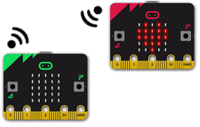
The micro:bit and other boards with Nordic chips support an easy-to-use, peer-to-peer radio messaging system. This is the same system used by MakeCode, so MicroBlocks and Makecode programs can exchange information via radio.
A radio messages consist of a short text string, a number, or both (a pair).
Using different group codes (0-255) allows multiple radio projects to operate simultaously in classroom settings. A group is an independent communications channel. Each microcontroller sends and receives messages to others in its own group. Any messages being exchanged by other groups are ignored.
The group is set to zero by default. You don't need change to another group unless people nearby are already using group zero.
¶ radio send number

Send a message containing a number.
On the receiving end, the number is read with the radio last number block.
¶ radio send string

Send a short text string (up to 19 bytes). You can send longer messages by breaking them into 19 byte chunks.
On the receiving end, the string is read with the radio last string block.
¶ radio send pair

Send a message containing both short text string and a number. The string can be used to specify what number means -- for example "light = 10" might mean that the light sensor reading is 10.
On the receiving end, the string part of the message is read with the radio last string block and the number part with the radio last number block.
¶ radio message received

Return true when a new radio message is received.
This block is often used in a when hat to process incoming radio messages. For example this script prints incoming text messages:

¶ radio last number

Return the number part of the last radio message received. Return zero if the message did not contain a number.
¶ radio last string

Return the string part of the last radio message received. Return the empty string if the message did not contain a string.
¶ radio set group

Set the group number (0-255) used to send and receive messages.
A group is an independent communications channel. Messages sent by a microcontroller in a given group are received by all other microcontrollers in that group. Messages exchanged by other groups are ignored.
The default group number is zero. The microcontroller reverts to that group when it is reset.
¶ radio set power

Set the radio transmission power level (0-7). Zero is the weakest and has the shortest range.
Using a low power level might be used in a game where the goal is to find a hidden microcontroller. Since the power level is low, the searcher must get close to the hidden microcontroller in order to receive its signal.
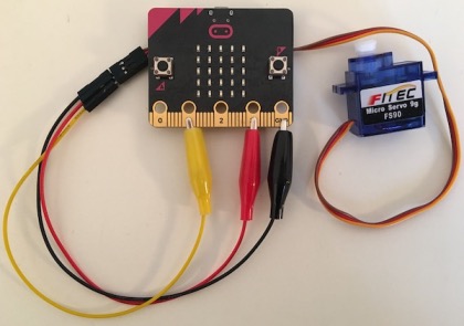
A servo combines a motor and digital controller into a single unit. There are two kinds of servos. A position servo moves the servo arm to a fixed position (angle) and holds that position. Position servos have a limited range of anglular motion, usually -90 to +90 degrees.
A continuous rotation servo motor turns continuously. The speed and direction of rotation (clockwise or counterclockwise) can be controlled.
Both types of servo are controlled a series of digital pulses on the control line. The width of the pulse determins either the angle of the position servo or the speed and direction of the continuous rotation servo.
The set servo to degrees command is intended for use with position servos while the set servo to speed block is meant for use with continuous rotation servos. However, since the same control signal operates both types of servo, a position servo will respond to the speed command or vice versa. It is up to the the user to use the command that makes sense for the type of servo they are using.
 |
|---|
TinkerCad Video
¶ set servo degrees

Sets the angle of a position servo. It takes time for the servo to change positions, so it's good add a **wait milliseconds" block after this block. The servo will remain at the given angle until told to move to another postion.
¶ set servo speed

Sets the speed of a continuous rotation servo. The absolute value of the argument determines the power level and negative values make the servo rotate in the opposite direction from positive ones.
Many servos stall (stop turning) if the power level is too low. There is a lot of variation between servos, you'll need to experiment to find the power levels that work best for your servo.
¶ servo stop

Stops sending servo control pulses. This will make continuous rotation servos stop turning. Position servos will remain in their last position.
The stop button in the IDE will also stop sending servo control pulses, which can be helpful if your servo has gotten out of control.
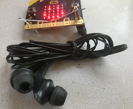
Many of the supported boards have a built-in speaker that can be used to play tones and music. Some boards (e.g. micro:bit v1) lack a built in speaker. The Tone and Rington libraries can be used on such boards by attaching headphones or a passive piezo buzzer to an output pin.
¶ play note

Play the given note in the given octave for the given number of milliseconds. Note names are A-G (upper or lowercase) optionally followed by # for a sharp.
¶ play midi

Play the note specified by the key number on the piano keyboard (0-127) where middle C is 60. This block is useful when doing mathematical transformations of music (e.g. transposing to another key).
MIDI is short for "Musical Instrument Digital Interface", an industry standard for controlling synthesizers, drum machines, and other electronic musical devices.
¶ play frequency

Play a note specified in Hertz (Hz). Middle C is about 261 Hz, the A above that is 440 Hz (the note to which orchestras tune).
¶ start tone

Start playing a tone specified in Hertz (Hz) continuously.
¶ stop tone

Start playing a tone that was started with start tone.
¶ attach buzzer

Specify the pin used to play tones. A piezo buzzer or headphones are connected to this pin. On boards with built-in speakers, the built-in speaker will be used if this block is omitted.
The Nokia Ringtone format (also called RTTTL) was created to encode simple tunes as Nokia phone ringtones as compact, human-readable text strings.
If you know the notes of a song, you can turn it into a ringtone that MicroBlocks can play.
A ringtone consists of a header (title + default values) followed by a sequence of notes and rests separated by commas. Each note specifies the note name, octave, and duration. For example, 2c4 represents a half-note middle C. For further details, see the Wikipedia article Ring Tone Text Transfer Language.
A helpful Arduino community member gathered over 10,000 ringtones, of varying quality, from the internet. Here is a slightly edited version of that giant ringtone collection (offensive titles have been removed).
¶ play ringtone
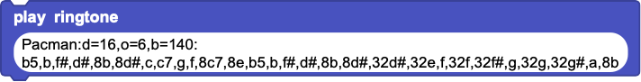
Play the given ringtone string.
¶ current song name

Report the name of the currently playing ringtone song.