¶ Overview
Remote Control is a very handy technique used when controlling projects. Whether it is a robotic car, a house energy management system, or a weather station; they all could benefit from this communication / control method.
Remote Control can be implemented using any of the available communications capabilities of the microcontrollers at hand. Bluetooth, Serial Comms, GSM, RF, WIFI are methods that come to mind. In this tutorial, we will be specifically focusing on the use of WIFI based remote control, specifically one that makes use of the User Datagram Protocol.
And it is no surprise that we can learn how to make use of this technology with the help of MicroBlocks WIFI and UDP Libraries. While other programming environments may offer the same functionality, MicroBlocks implementation is specifically simple and straightforward.
"In computer networking, the User Datagram Protocol (UDP) is one of the core communication protocols of the Internet protocol suite used to send messages (transported as datagrams in packets) to other hosts on an Internet Protocol (IP) network. Within an IP network, UDP does not require prior communication to set up communication channels or data paths." - courtesy of Wikipedia.
We will learn how to transmit and receive UDP messages and act on the message content by turning an on-board LED on and off. Once you master this exercise, you can then implement other more complex control systems on your own.
To make things more interesting and also to showcase one of the greatest features of MicroBlocks - PORTABILITY, this tutorial will make use of five different microcontrollers. You can experiment with whatever is available to you.
Microcontrollers used in the project have several common features:
- they all support WIFI
- they all have an on-board LED
- some of them feature a button, that we will use in our project
In the picture below, we show all five microcontrollers with the locations of the LEDs and Buttons marked.
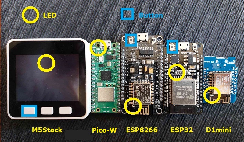
In addition to the program to control the various microcontrollers, we will also provide you with a demo program for an Android phone, so you can use it as a remote control device to participate in this exercise and to send and receive messages.
NOTE: All devices mentioned here, with the exception of the Android phone, use the SAME EXACT MicroBlocks PROGRAM to control the LEDs.
This is a great example of the WRITE-ONCE use on MANY capability offered by MicroBlocks.
¶ Parts
To complete this tutorial you will need:
-
one or more microcontrollers with WIFI capability and a physical button. Depending on what is available to you, any one of the ones shown in the picture above would be fine.
-
an Android Phone (optional)
If you only have a single microcontroller with WIFI capability, then you can use it in combination with the Android phone APP. Worse case, if you have no microcontrollers availabe, but own an Android phone, then you can still experiment with this tutorial using your phone.
Please make sure that you have at least one microcontroller with a button on it (M5Stack, ESP8266, ESP32). The button is used to generate the message to be sent, and without it you will not be able to send messages.
Alternatively, you can also get by with an Android phone and a microcontroller without a button.
¶ Making the connections
Since this exercise makes use of the WIFI capability of the devices in use, there will be no need for physical cabling.
As far as the WIFI availability goes, you can start by using the WIFI provided by your house router.
Later, we will also describe a way you can create your own WIFI HotSpot using the the same devices and provide your own WIFI signal. This will be handy if you plan on operating in an area without a WIFI service present.
¶ Scripts
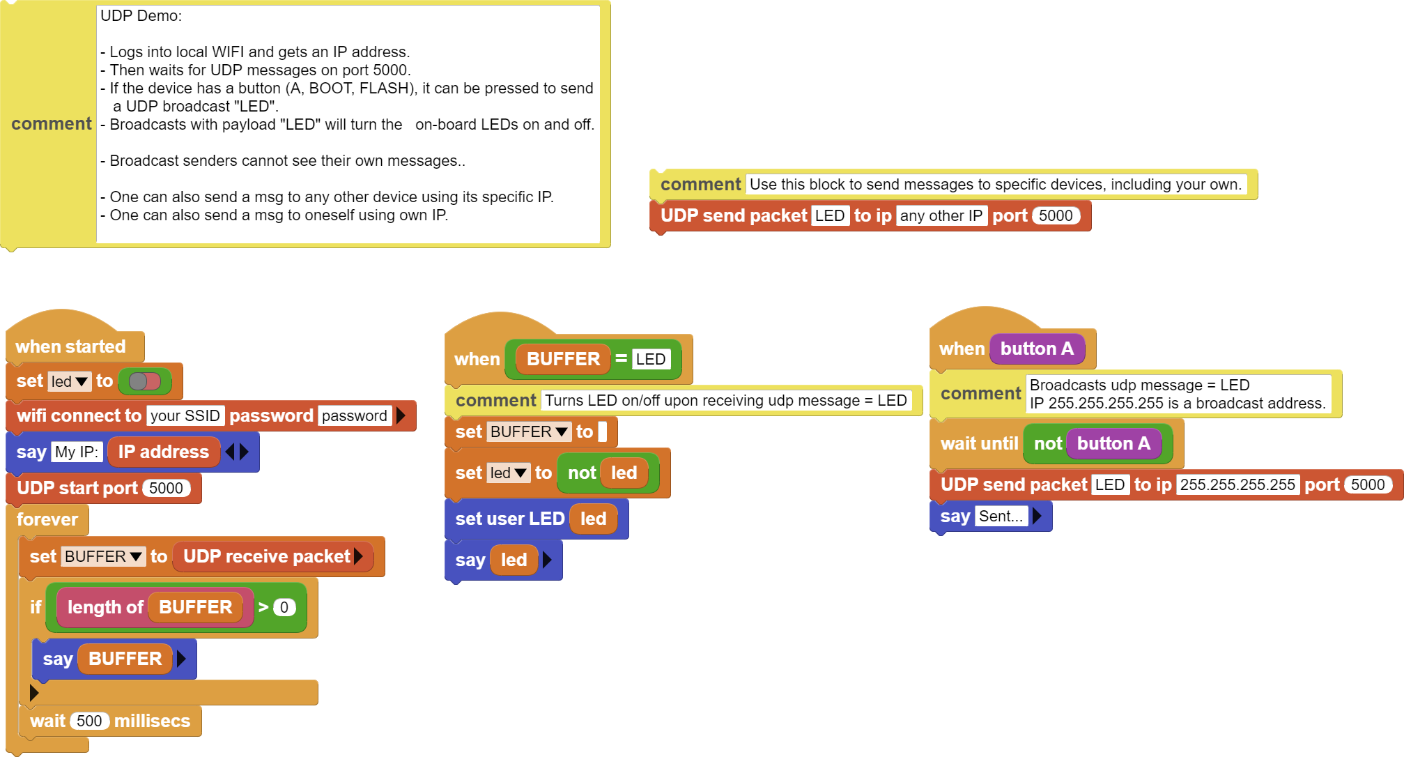
As mentioned above, this execise uses a single project code for all of the microcontrollers used. They all will run the same exact program and do the same exact thing: turn the on-board LED on and off upon receipt of UDP messages and send messages when the button is pressed.
In the script picture below,
-
when started blocks handle the WIFI signon and display the IP address obtained from the local router. Then the script enters a loop of receiving messages and displaying them on the IDE.
-
when button A block sends an UDP broadcast message with the payload of "LED".
-
when BUFFER = LED block acts on the the LED message received and toggles the on-board LED.

We have provided a separate UDP send block that you can use to exercise the option of sending an UDP message to yourself or to another specific device.
In order to do that, you need to make a note of the displayed IP address at the start of the program and then direct your message to that specific address for respective microcontrollers in your test case.
If you are using the Android APP, it will have its IP displayed on top of the screen.
¶ Process
We have already mentioned the anticipated simple behavior of our project:
- Sign-on to the local WIFI network and get an IP address
- Then wait for "LED" UDP messages received and toggle the LED.
- If the on-board button is pressed, send a broadcast "LED" message to all participant devices. This should make them toggle their respective LEDs.
Remember to replace the SSID and Password in the program with your specific information.
It may be helpful to briefly review the User Datagram Protocol (UDP) operations to get a better feel for all the action in our tutorial. You can refer to the UDP article in Wikipedia or else for a more detailed treatment of the topic.
¶ UDP Basics
(courtesy of Wikipedia)
In computer networking, the User Datagram Protocol (UDP) is one of the core communication protocols of the Internet protocol suite used to send messages (transported as datagrams in packets) to other hosts on an Internet Protocol (IP) network. Within an IP network, UDP does not require prior communication to set up communication channels or data paths.
UDP uses a simple connectionless communication model with a minimum of protocol mechanisms. UDP provides port numbers for addressing different functions at the source and destination of the datagram. It has no handshaking dialogues, and thus there is no guarantee of delivery, ordering, or duplicate protection.
UDP is suitable for purposes where error checking and correction are either not necessary or are performed in the application. Time-sensitive applications often use UDP because dropping packets is preferable to waiting for packets delayed due to retransmission, which may not be an option in a real-time system.
UDP Ports
Applications can use datagram sockets to establish host-to-host communications. An application binds a socket to its endpoint of data transmission, which is a combination of an IP address and a port. In this way, UDP provides application multiplexing. A port is a software structure that is identified by the port number, a 16-bit integer value, allowing for port numbers between 0 and 65535. Port 0 is reserved but is a permissible source port value if the sending process does not expect messages in response.
¶ UDP in our Project
MicroBlocks implementation of the UDP protocol is manifested in the UDP Library. There is no special requirement prior to using the protocol, other than devices involved have to be present on a shared IP network, in our case our local WIFI.
Let's review the library blocks used:

This block sets up the script to listen to the UDP messages on the designated port. The device's own IP address and the specified port number make up a socket, and uniquely identify the device and any software service it provides. As per above:
- if a UDP broadcast message addressed to port 5000 is sent,
- OR a UDP message addressed to device's IP and port 5000 is sent
...our script will see and receive it.

This block is used to send out UDP messages to the designated IP address and port. As per above, IP address 255.255.255.255 is a special broadcast address, and it will be used to access all IP devices on the local subnet. This makes it easier to send messages without bothering with each devices specific IP address.
Note that in MicroBlocks, broadcast messages are not seen by the sender device. However, in the MIT AI2 APP, broadcasts are seen by the sending phone.
Messages can also be sent using the specific IP address and UDP port number of the destination device, even to one's own IP address.

Whenever a UDP message is received, this block will contain its content. By checking if its length is greater than zero, we can query the result of the UDP transactions.
This block also provides a binary data boolean option that allows one to receive any type of data.
There are some other blocks in the library that are not used by our project. These are pretty much self explanatory.
 - UDP message sender IP
 - UDP sender port
 - Stop processing UDP
¶ App Inventor APP
We have provided an Android companion APP for the UDPDemo program. It will provide you with extra flexibility if you only have a single or no microcontroller to work with. You can send messages between the microcontroller and the cell phone APP; or just send messages from the phone to itself. In addition, it will allow you to exercise some of the more advanced features of the UDPDemo project.
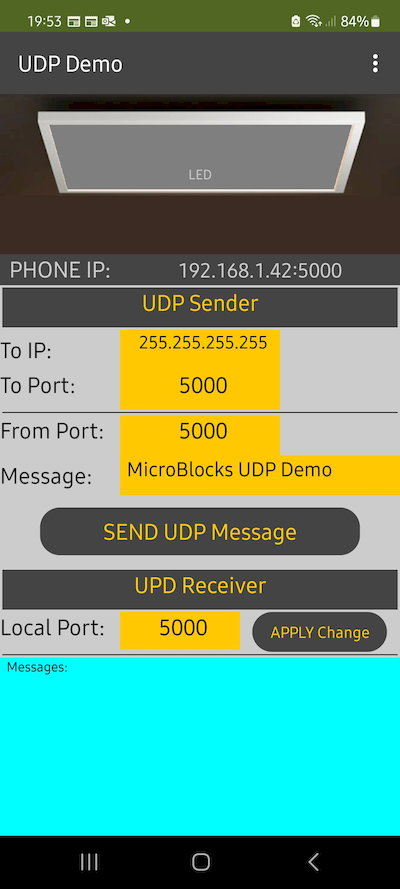
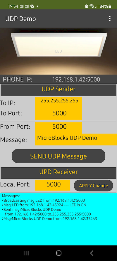
Below two images display the APP GUI at the start of the program and upon receiving an UDP broadcast message, where the simulated LED is turned on.
¶ APP User Interface
The APP GUI consists of four parts:
- Top button / image combination: used to generate UDP broadcast messages to toggle LEDs of receiving devices and also display the LED actions for received messages.
- UDP Sender Area: Provides detailed control for the destination IP address, destination and local Port numbers, and Message text content of the UDP messages. This area is mainly used to test various UDP message options and experiment with other devices with regards to IP and Port numbering combinations.
- UDP Receiver Area: Provides the ability to modify the UDP port the device is listening to.
- Message Display Area: All exchanges of the program and any error messages are displayed in this area.
¶ How to Use the APP
While the APP GUI provides many details, the actual use is very simple. Let's break it down to various tasks and try it out:
¶ Receive UDP Messages
There is nothing to do. The program will start receiving messages immediately upon execution. The IP address is obtained automatically and any UDP messages destined for port 5000 will be received and displayed.
Port number can be changed via the Local Port entry field in the UDP Receiver Area. Upon change, the APP will start processing messages addressed to the new Port.
For a message to be received, it will have to be sent to either the broadcast address of 255.255.255.255 or the phone's specific IP address. In either case, the Port number has to match the Local Port selected.
¶ Send UDP Broadcasts to control LEDs
Again, there is nothing special to do, but tap the LED image at the top of the screen. An UDP broadcast message to destination IP = 255.255.255.255 and destination Port = 5000 will be sent. Any devices on your local subnet listening to UDP port 5000 should receive these messages and toggle their LEDs accordingly. This includes your Android phone. You will see your own LED toggle, each time you tap the LED image.
This option is set to always send to broadcast address and Port = 5000. It is a safe way to test the APP exchange.
If you want to modify any IP or Port options, please refer to Send Customized UDP Messages below.
¶ Change Local UDP Port
The APP defaults to listening on UDP port 5000. However, this can be changed by entering a different Port number into the Local Port field of the UDP Receiver Area of the APP. After tapping APPLY Change, the new port will be operational immediately.
¶ Send Customized UDP Messages
This is the area where you can gain total control of the UDP messages and parameters.
You can designate destination IP addresses and Ports, change your own Port number for messages to be sent, and customize the content of the message text.
You should have a good grasp of all the fields mentioned above before playing around with this option. There is no harm that you can do to anything. However, by setting parameters in an unexpected manner, you may end up doing what you did not intend and chase around looking for messages that were not received at the right destinations and ports.
If you want to try a failsafe exercise, try sending yourself a message:
- Set the To IP to your own IP address
- Set the To Port to 5000 or the same port number as selected in Local Port
- Leave From Port as 5000 (this value will not matter in this exercise)
- Set Message to LED
Then tap the SEND UDP Message button.
You should see a message sent notification in the Messages Area at the bottom of the screen.
And your LED image at the top of the screen shoud toggle ON or OFF depending on what it was before. You can send the message repeatedly and observe your LED toggle accordingly.
Also try sending a message with a different Message text content. In this case, since the message text is not "LED", your LED will not toggle. However, you will get the message notifications in the Message Area at the bottom of the screen.
Now if you feel adventurous, you can try sending a message to your microcontroller device.
Same principles apply! We'll let you experiment and have fun.
¶ No WIFI, No Problem - Let's fire up our HotSpot !
We have mentioned earlier that there may be cases where the environment you want to exercise control over your devices might not have a WIFI signal available. Specially, if you are in the woods or out in nature or in a far away from civilization location. No worries! You still will be able to experiment with this tutorial by following the directions provided here.
¶ My own WIFI Signal
Let's see how we can activate our own WIFI signal.
You will need at least a single microcontroller that is WIFI capable. If you also have an Android phone, then you are in business.
To create our own WIFI signal, we will use a modified version of the MicroBlocks program (UDPDemoHS.ubp). Also, while in the previous version of the exercise we were using a single program for all devices; this time we will need specifically two versions:
- WIFI Hotspot version of the program - this will run on s single device and act like your Router: providing WIFI signal and DHCP services for address assignments.
- and the original version used earlier
- Of course, if you are using your Android phone, you will still need the APP for that.
¶ How Does it Work
To better visualize the project setup, let's take a look at the picture below.
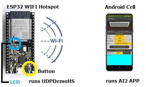
We have used an ESP32-Wroom microcontroller as the WIFI Hotspot provider. It is running the UDPDemoHS.ubp MicroBlocks program. This has to be the ONLY device running this version of the program. In the MicroBlocks program, you will specify a NETWORK Name and a PASSWORD that will be used to define and control access to the WIFI HotSpot.

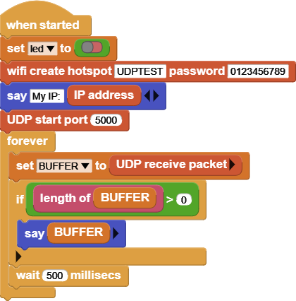
The block example provided shows the Network Name as UDPTEST and the PASSWORD as 01223456789. Feel free to change these to anything you want.
The UPDemoHS.ubp program differs from the original version only the in fact that it creates a WIFI HotSpot. Since there should only be a single WIFI network operational, only one device is permitted to run this program. Here is the when started section of the program with the Hotspot creation:
All other microcontrollers, if any, should be running the UDPDemo.ubp program. For these devices, you need to modify the SSID and Password in the MicroBloccks program to the one belonging to the WIFI HotSpot you have created.
On the ESP32 in the picture, we have marked the on-board LED and the button that will be used to send UDP messages. Whenever the device receives an UDP message, its LED will toggle.
For simplicity, we have only added an Android smart phone running the MIT AI2 APP. As before, it will toggle the LED image at top of the display each time it receives an UDP message. You can also tap the image yourself and cause it to toggle the LED.
Remember that the Android version of the UDP implementation allows for broadcasts sent from the phone to be received and acted upon by the phone. Hence you can control the
LED on your phone from the same phone. This is not possible with the ESP32 device.
If you have other microcontroller devices, you can add them to the environment. They all should be running the earlier version of the UDPDemo.ubp Microblocks program. And they all will behave as before, toggling their respective LEDs with each UDP message received.
¶ Let's Activate the new Network
When the ESP32 starts running, it will create a WIFI Network named UDPTEST. You can see this on your PC WIFI network scan, as well as your Android phone WIFI scan. Here is what you should be looking for:
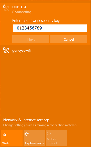
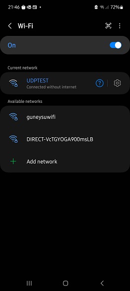
For each of the microcontrollers (except the one that is acting as the WIFI HotSpot) that you will be using in your own test, you need to modify the MicroBlocks program WIFI signon to use the new WIFI network credentials: UDPTEST / 0123456789.
If you are using an Android phone, then its WIFI also needs to signon to the new network: UDPTEST / 0123456789.
Once you complete these steps, then everything should run without a problem.
Things you can try:
-
Press the button on the ESP32 and you should see the LED in your phone APP light up. Again and it should go off.
-
Likewise, if you tap the LED picture in your phone APP, the ESP32 LED will light up. Your phone LED will toggle to the opposite status of what it was just before.
-
Keep repeating till you get the hang of it.
-
And if you are feeling adventurous, try sending device to device messages using their respective IP addresses and Port numbers.
If you have created a WIFI HotSpot and tested everything with it, remember to shut it down and login your devices and phone to your normal WIFI network. Otherwise, you will not be operating as you were before the exercises and wonder why nothing is working as usual.
¶ Discussion
UDP messages are not guaranteed for delivery. Due to the network conditions, you may observe instances where not all devices toggle the LED at each button press. This would leave some of your boards with LEDs on and others with LEDs off. How can you make all boards go to the starting condition of all LEDs off?
This project sends out messages at each button press. This requires that you have at least one microcontroller with a buttons. How can you modify the project to eliminate this requirement?
What do you think is the longest message you can send?
Current project toggles the microcontroller's built-in LEDs. How would you modify the project to turn on/off an external LED attached to the microcontroller?
If you managed to achieve the above challenge, you can also use a RBG LED, instead of a normal single color LED. How would you modify the project to control the RGB LED to display any color desired?
The Android APP is written in MIT's App Inventor. It behaves very similar to the microcontrollers used in the project. If you are familiar with MIT AI2, can you modify the APP to control the RGB LED from the phone?
Last three challenges are pretty complex and require quite a bit of know-how. If manage to get them working, you have done extremely well.
¶ Pointers / Troubleshooting
If you have multiple WIFI capable microcontrollers that you will be working with, you will find it easier to load the programs on them one at a time.
However, if you are comfortable with it, you can run multiple sessions of the MicroBlocks in the browser and connect a microcontroller to each one.
For that you will need a way to hook up several USB devices to your PC. This method will also come in handy later, in case you want to try out the individual message sending between specific devices. To do that you will need to know their acquired IP addresses. When the MicroBlocks program runs, it will always display the acquired IP address.
If you manage multiple devices all at once, remember to keep notes on which device is connected to which USB port by its name and driver info. Things can get confusing very quickly.
In the first mode of the tutorial, where you are on your home network, you will normally see home network addresses in the range of 192.168.1.nnn. If for some reason you have modified your home Internet router to allocate a different range of IP addresses, then you may have addresses that look different.
If you are trying out the HotSpot version of the tutorial, you will need to be aware of the differences in IP addresses created and used.
In the HotSpot mode of the tutorial, the designated microcontroller will create a network and dish out a different set of addresses. These will normally look like 192.168.4.1 for the router, and 192.168.4.2 and onwards for the other devices, including your Android phone (if you use one for the tutorial.)
In the HotSpot mode of the tutorial, remember to activate the new network first, with the ESP32 in our example. This will set up the environment ready to assign addresses for the joining devices. You should only hook up your phone's WIFI to the new network after you activate it. Otherwise, your phone WIFI scan will not see the network with the SSID = UDPTEST.
Keep in mind that during both versions of the tutorial, you are never accessing the Internet. As a matter of fact, in the Hotspot version,, there is not even any Internet connectivity available, as you will notice in the status displays of the WIFI networks. All traffic exchange happens within the private domain of your home network and of the new network you create with the HotSpot option.
There are ways to access the Internet under both operating modes. However, that is a very complicated topic to get into for the purposes of this tutorial. Anyone interested can research NAT (Network Address Translation), Proxy services, Private and public Internet addresses and try to make sense of it all.
A good way to get rid of the unwanted network entries in your PC and in your phone is to select the option to FORGET that network. You will find this option in the WIFI connectivity configuration section of your devices.
¶ What can go wrong
Since UDP is a connectionless connectivity model and there are no guarantees of datagram delivery, one thing that comes to mind is "lost messages". UDP messages do NOT get queued or retried! They simply get discarded.
Don't be surprised if with every push of your microcontroller (or phone) buttons, not all devices end up toggling their LEDs; or do so intermittently. It is the way it is!
It is a bit confusing, but MicroBlocks WIFI and Androd WIFI handle broadcast messages differently. This in itself is not a problem! But it helps to keep this point in our minds, as we work through the exercises. Broadcasts sent from the microcontrollers do not show up in the device that originated the broadcast. On the other hand, Android phones will broadcast a message and also see it and act on it. Therefore, if you use a phone with this tutorial, you will see that every time you tap the LED image on the phone, it will toggle its status. Whereas the microcontrollers will never light up their own LEDs with their own messages.
The project programs are written to toggle the LEDs. This means that there is no forced way to set a LED to a desired state: ON or OFF. In the beginning of the programs, all LEDs are OFF. But as the exercises continue, they may get out of synch due to lost messages etc, as explained above. So any LED's subsequent behavior is totally dependent on what state it was in just before the last message arrived.
As you experiment with the UDP messaging, broadcasting, IP and Port Settings, you will invariably change some of these parameters. It helps to keep in mind that UDP messages need to have a matching destination address AND a Port number. Once you set a device to listen to a particular Port number, it will NOT see messages destined to other port numbers. So, if you start not getting intended messages, check to make sure your sending and receiving devices are using correct addresses and ports.
And remember, the best way to restart everything is to RESET everything.
Enjoy!
¶ Project Download
UDPDemo MicroBlocks Program For This Tutorial - Install on each WIFI capable microcontroller you want to test with.
UDPDemoHS MicroBlocks Program For Creating your own WIFI Network - Install ONLY on a single WIFI capable microcontroller you want to act as your new network Router.
MIT AI2 Android APP Source - Customize the APP using MIT AI2.
 |
MIT AI2 Android APP APK - Sideload this file to your phone. Might require permission to install unknown APPs. |
|---|