¶ Overview
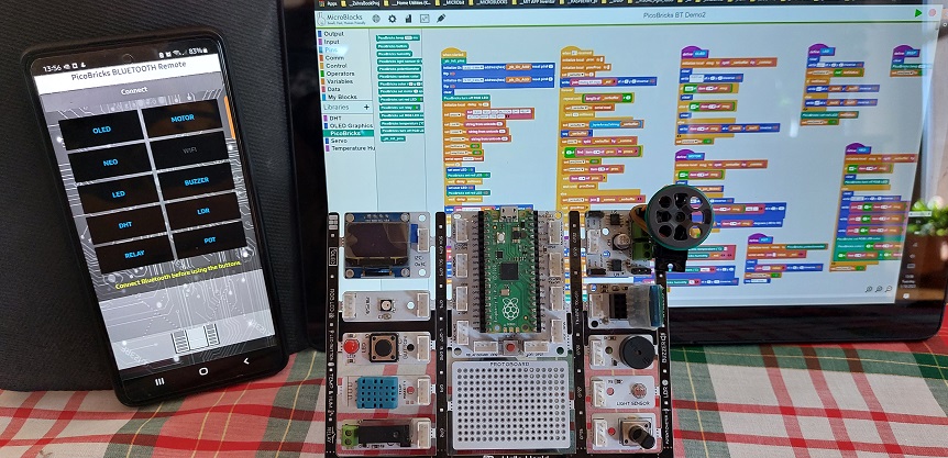
This project will demonstrate how to interface and remotely control the PicoBricks kit and its modules from an Android mobile phone using the classic Bluetooth interface.
The Android APP will allow you to select each component of the PicBricks kit and control it from the phone. You can display messages on the OLED display, run the Servo motors, turn the LEDs on and off, set the colors of the RGB LED dynamically, and emit tones from the piezzo speaker. In addition, you can also read the ambient light, temperature and humidity levels, or control the AC relay switch to activate any devices you may have attached to it. The potentiometer values can also be read in real-time, while you are adjusting the pot position.
¶ Parts
To make the entire project work, we need many parts to work in an integrated manner:
¶ PC Side:
- The PicoBricks kit - with all the modules attached is the main component. It should have the pico processor mounted in its socket with the USB port pointing up.
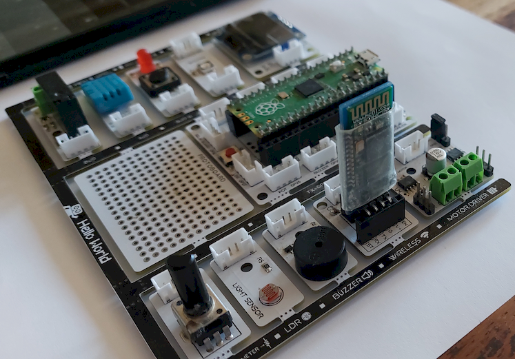
- HC05 Bluetooth component - need to add to the kit to enable communications with the Android mobile phone. There is a special slot on the kit marked WIRELESS. Place the HC05 with the circuit components facing to the right. If your HC05 is a 4-pin version, insert it such that the bottom and top pins of the socket is left unused. Your kit with the HC05 installed should look like this:
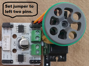
- Servo motors - If you are going to use servos, they need to be attached to the Motor Driver module. By default, the project will operate with the Servo #2 attached to the top edge of the Motor Driver module. Servo cable colors are GND-:brown, PWR+:red, SIGNAL:yellow. Depending on if you are using the top or the bottom servo connection, you need to set the corresponding servo/DC selection jumper to the leftmost two pins. Make the connection as shown in the picture below.
- USB Cable - Connect the pico processor with an USB cable to your PC.
- MicroBlocks program (PicoBricks BT Demo 2) - Load it to MicroBlocks running on your PC.
This completes our setup for the Pico board.
¶ ANDROID Side:
- Enable Bluetooth on your mobile phone - If your phone's Bluetooth service is not enabled, do so now. Then, you need to PAIR your phone Bluetooth settings with the HC-05. Refer to your device’s instructions on how to do that. Once you are paired, you can start using the Demo APP. Your HC05 light should be blinking in rapid fashion.
- AI2 program (PicoBricks_Remote_BKGND_newSVR.apk) - Sideload this APP to your mobile phone. you may have to provide installation permission to complete the install.
¶ ANDROID APP Use
The APP is written in App Inventor and can be totally customized. Its GUI will allow you to exercise control over every component of the PicoBricks Kit.
In the APP, click Connect to establish the bluetooth connection to the PicoBricks. In the Bluetooth devices list displayed, select your specific HC05. When the connection is completed, the Connect prompt with change to an orange colored CONNECTED... prompt. You’ll see your BT module lights switch to a double blink every two seconds. Now you are ready to test.
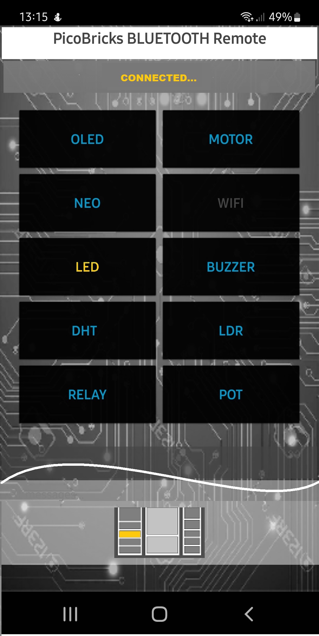 |
The screen layout of the APP resembles the PicoBricks board layout, with buttons representing the modules and a module map at the bottom of the screen. When you select a module to test, its name will turn yellow in the button and the corresponding module location on the map will display the module you are exercising in orange color. |
|---|
¶ Module Controls
Modules LED, DHT, RELAY, LDR, BUZZER operate with a single click of their respective buttons on the phone. LED and RELAY will turn on when tapped, and turn off at next tap. DHT, LDR will provide a sensor readout data when tapped, which is displayed on the phone. BUZZER will make a short buzz sound.
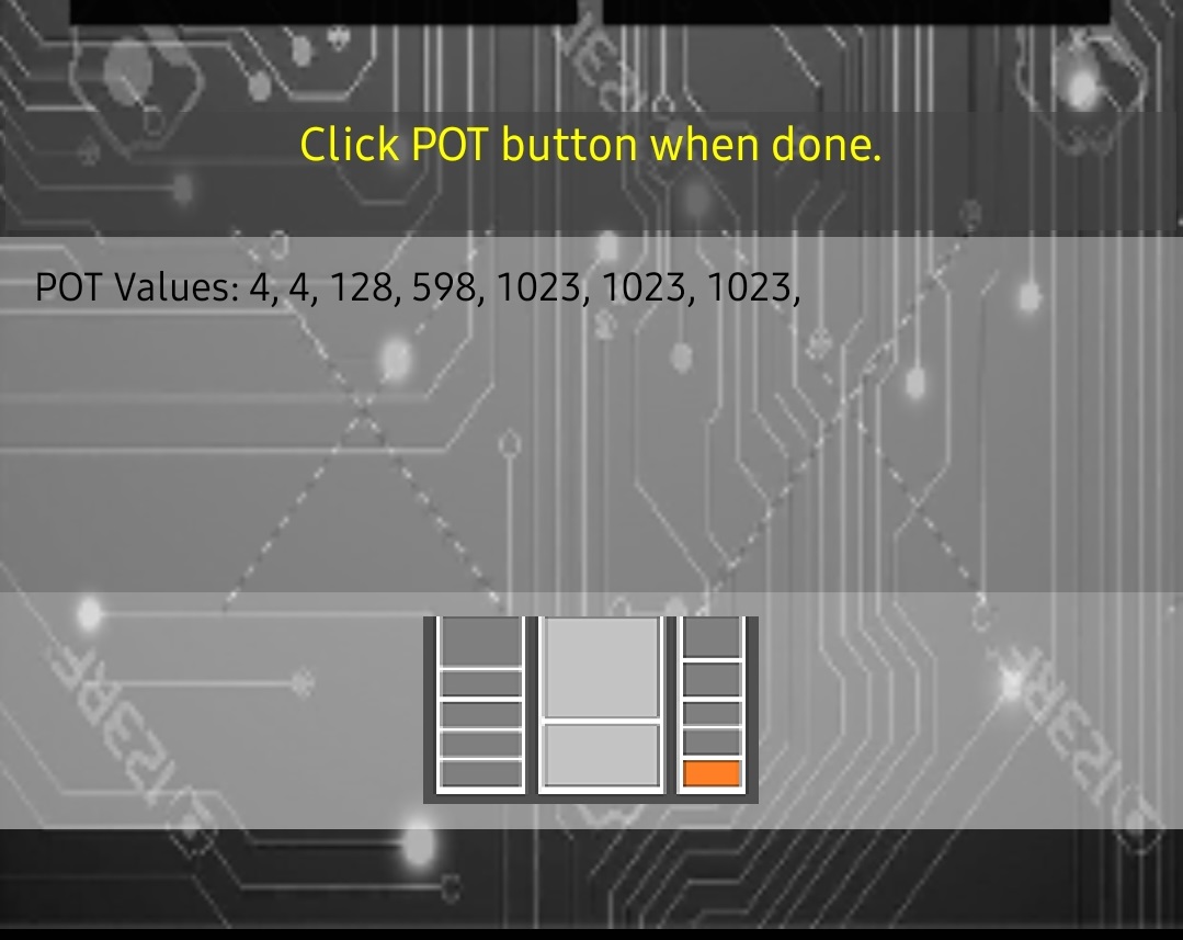
Module POT will prompt the user to operate the potentiometer on the PicoBoard and display pot values on the OLED and the phone. Tap the POT button again when done.
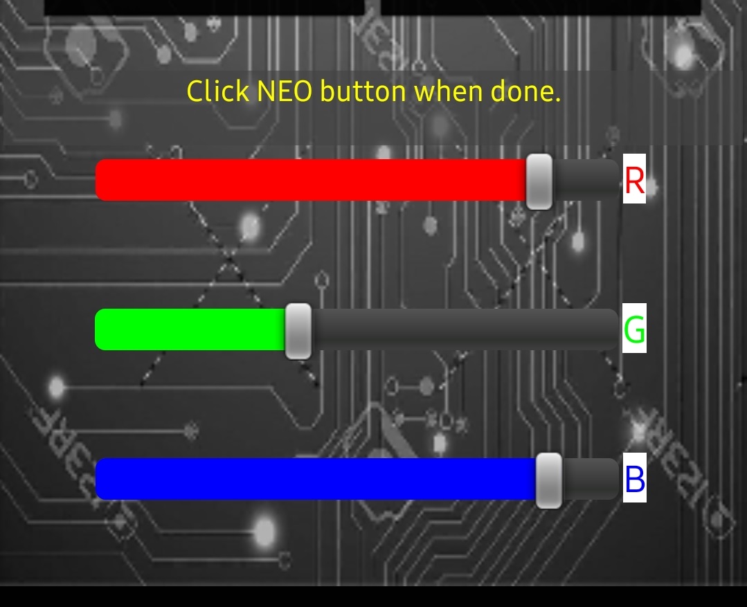
Module NEO will display three sliders to control the RGB colors. As you adjust them, the NEOPixel on the PicoBricks and the NEO button background will change color simultaneously, showing you the resulting color selection. Tap the NEO button again when done.

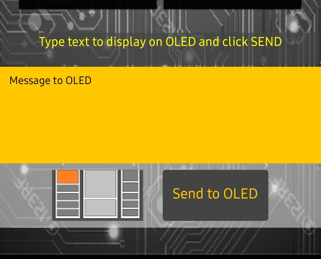
Module OLED opens up a text entry area where you can type short messages. As you touch the text entry area, the Android keyboard will pop up for data entry. When you are done entering text, hide the keyboard and then tap the “SEND TO OLED” button. your message will be displayed on the OLED display of the PicoBricks. Tap the OLED button again when done.
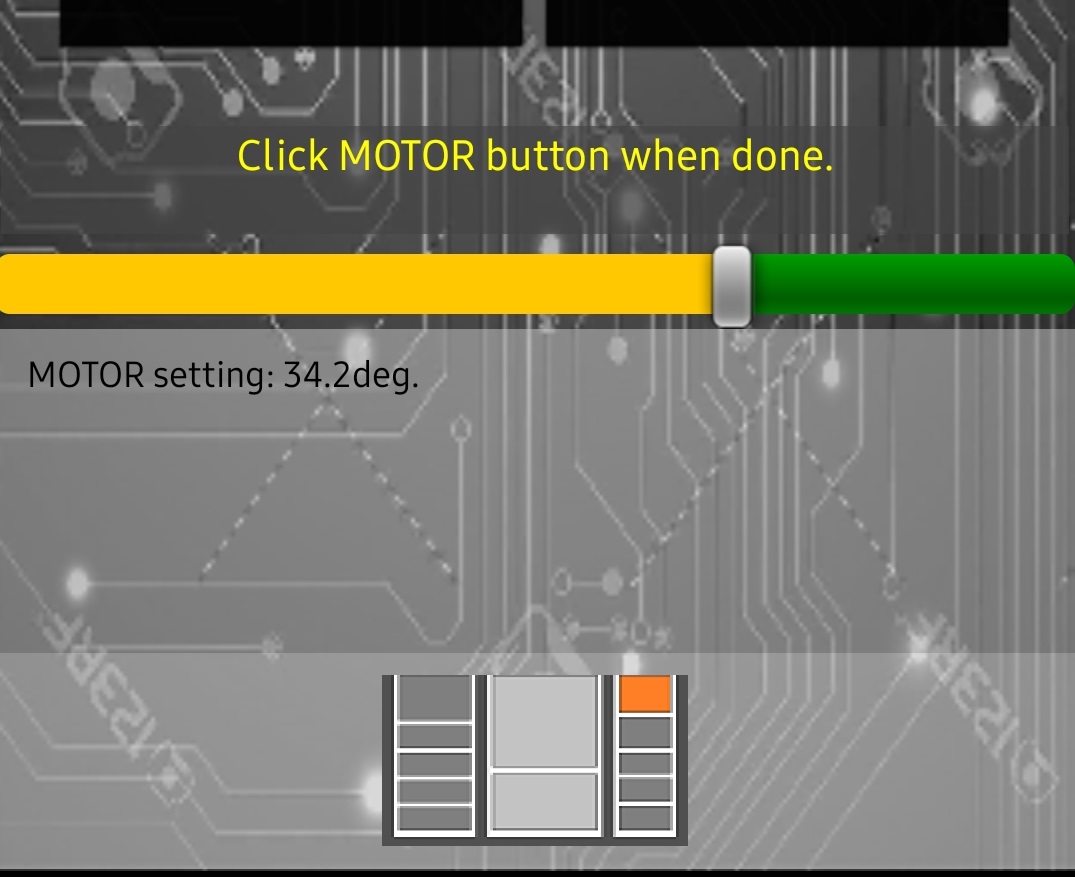
Module MOTOR will display a slider that will let you control a SERVO motor attached to the PicoBricks. NOTE that the demo only operates SERVO #2. You can exercise a -90 to +90 degrees of motion with the servo motor. Tap the MOTOR button again when done.
It is possible that during the project use Bluetooth connection may drop or you may experience message synch problems between the phone and the PicoBricks unit. These programs were written to demo the information exchange concepts and do not contain rigorous error checking. Best course of action is to restart everything and try again. For more info on Bluetooth operations, refer to the Notes at end of this article.
¶ Scripts
The best way to understand the interaction between the PicoBricks and the Android Phone is to review the overall design in regards to the message exchange between both sides.
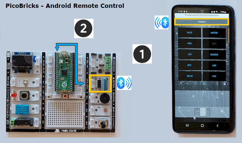
Above picture annotates two sets of interaction:
-
Bluetooth communication between the Android Phone and the PicoBricks:
This is the main link between the two pieces of hardware and forms the core of the remote conrol implementation. Both sides exchange messages over this link. On the Android side, the onboard APP uses Bluetooth exchange to communicate to the mobile phone's Bluetooth service, which in turn relays these to the PicoBricks Bluetooth module it is paired with. -
Serial communicatioon between the PicoBricks Bluetooth module and the MicroBlocks program running on the Pico processor.
The onboard Bluetooth module of the PicoBricks kit uses a serial link to the onboard MicroBlocks program to exchange messages arriving via the Bluetooth link. So from a MicroBlocks program point of view, any Bluetooth exchange in the program is happening over the serial port.
Having clarified the main message exchange principles, we can move on to study the program details.
Below is a picture of all the scripts in the MicroBlocks program. We will describe main implementation concepts to understand the program design. Then we will review a few of the scripts that handle the module controls to understand how the remote control is achieved.
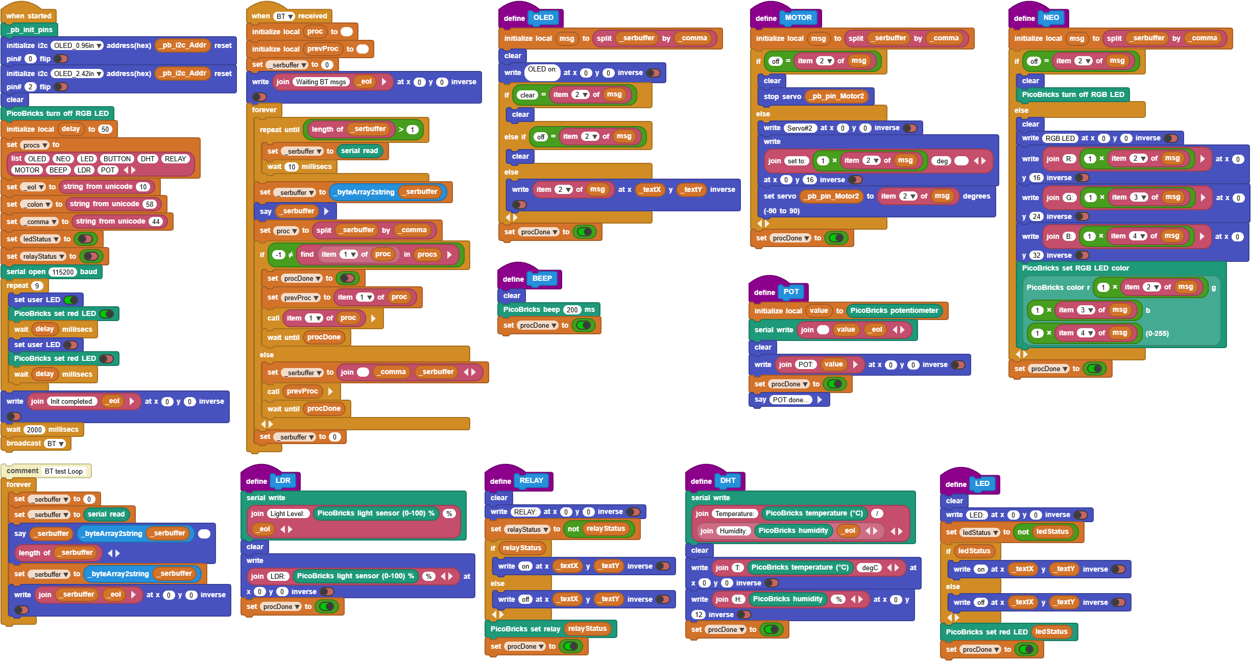
PicoBrick modules can be grouped into two categories based on their mode of operation:
-
Simple on/off types - these operate based on a command received and perform a single action: LED on/off, Switch on/off, Buzzer on/off etc.
-
Modules that generate or consume data - these are sensors, actuators or display modules that report values or can accept data sent to them and perform a function: DHT sensor reports temp and humidity, LDR sensor reports light levels, Potentiometer generates values, OLED displays text sent, etc.
Since the main interaction between the Android side and the PicoBricks side is message based, the first design decision is the establishment of commands to be exchanged. We decide on 9 commands to control the 9 modules: OLED, NEO, LED, DHT, RELAY, MOTOR, BUZZER, LDR, POT. Note that we have left out the BUTTON component, since there is no remote control involved. Also, while the WIRELESS component supports both Bluetooth and ESP01 WIFI modules, only one of them is operational at a time, Since we are using the Bluetooth module, we will leave out the ESP01 control and describe it in another project.
¶ Main MicroBlocks Scripts
Program operation on the MicroBlocks side consists of two main streams:
-
when started script - sets up display initialization, program variables and establishes the commands to be used. It also opens the serial port at 115200 baud to establish communications with the onboard Bluetooth module. Once done it broadcasts a "BT" message to start the main communication loop.
-
when BT received script - consists of a forever loop that reads the Bluetooth messages arriving at the serial communications port, looks them up in the process table and dispatches the responsible script to handle the specific command interaction.
It is perfect time to highlight a great MicroBlocks feature and a very useful programming technique: List lookups to dispatch commands.
Commands arriving at the serial port consist of two parts:
Command name + comma separator + additional info
eg: OLED,"Hello from MicroBlocks"
This information is stored in the _serbuffer upon completion of the serial port read.
We use the  block to extract the command portion from the received message and assign it as the process name.
Once we have isolated the command, we do a lookup in the process list for a matching command. This is the part I was referring to above, when I said "a great programming technique." Instead of using a series of 9 indented IF THEN ELSE blocks, we use a single list lookup block, to determine the name of the script that will handle the arriving command.
 searches the procs list for the presence of item 1 of proc. Remember that proc contains the serial buffer data separated by comma (as shown above). If the search is successful, a number indicating its position in the list will be returned. And if the command is not found, -1 will be returned.
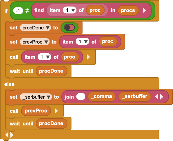 |
This script segment shows the entire lookup logic and the corresponding procedure call that will handle the command processing. It eliminates all the unnecessary IF THEN ELSE comparisons to find out what to do with the specific command. The great MicroBlocks feature we make use of here is the "call block" with the name of the command found in the lookup. It allows us to call any procedure based on the matching command. |
|---|
The wait until procDone block that you see after the call block is a synchronisation mechanism to make sure the communication loop waits till the command processing is completed.
¶ Command Implementations
Now that we have reviewed the overall flow of the program, let's examine a few of the specific scripts that handle the different command types. Note that every command script sets the procDone variable to TRUE at the end before exiting. This signals the main dispatch logic at the communications loop that processing of the command has been completed and the loop can be resumed to poll for the next message.
RELAY
RELAY command is a simple one. When it arrives, the program toggles a status variable to indicate the relay status. The result can be either true or false, meaning the relay is ON or OFF. Then depending on this status variable the relay is set accordingly. The relay setting is also written to the OLED display. Other commands that operate similarly are: BEEP, LED.
DHT
DHT command is just as simple as the RELAY command. The main difference is that this is a type of command that sends back the sensor readings to the Android phone. You can see this being done with the serial write block where both the temperature and humidity values are relayed back to the mobile phone. Following that the same values are written to the OLED display and the script concludes.
POT is another command that operates similarly. Except here, instead of the commands from the APP driving the PicoBricks module setting, the reverse is happening: the user modulates the potentiometer settings and the resulting values are relayed to the APP to be displayed on the mobile phone text area.
LDR is also operating just like the POT. The user modifies the local setting of the LDR sensor, which in turn changes its output. This result is relayed to the APP to be displayed on the text area.
OLED
OLED command is a bit different, such that it contains additional info in the incoming request:
OLED,"text to display".
This makes it a type 2 module as described earlier. Therefore, before the command is processed, it is broken down into parts using the comma as a delimiter. This separates the text from the command. Then the second part that contains the text to be displayed is further examined for three different possibilities:
- clear: indicates the screen should be cleared by remote control
- off: indicates the OLED use has concluded and the display should be cleared and the command processing terminated.
- any other text: display the text on the OLED screen.
The variable oledInUse with its TRUE or FALSE setting, controls the continuous writing to the display. One can send multiple OLED commands with different text and they will be written sequentially to the display. When the OLED button on the mobile APP is turned off, the the sequence stops.
NEO
NEO command is very similar to the OLED command. It also arrives with extra payload:
NEO, redValue, green value, blue value.
The red, green, and blue values are the settings for the RGB LED colors.
The RGB LED is set to the color that is generated by these three values.
When the NEO button on the APP is turned off, then the RGB LED is also turned off.
MOTOR.
Another command that operates similarly is MOTOR. It sets the servo to the degrees sent in the payload.
¶ APP Inventor Scripts
Please note that APP Inventor is a complex programming environment for the Android phones. The user is expected to be familiar with the programming concepts of the AI2. We do not have the bandwidth here to provide a tutorial in its use.
Just like we described the overall operational flow of the MicroBlocks program, we will provide some design and operational details for the App Inventor APP used in this project. Refer to the ANDROID APP Use section if needed.
AppInventor APPs are totally event driven. There is no main loop or main program logic! Everything happens based on events detected on the mobile phone in use. Therefore the APP is structured in chunks of scripts that each individually handle various events.
As you look at the APP GUI, you will notice that the main screen consists of many buttons, labels, text areas, and images. All these are acting as active components that have scripts for actions associated with them. So when you press a button, there is a scripts that gets run to deliver a particular action coded for that button.
Keeping this relationship of the GUI to the scripts in mind, let's review a few key design concepts.
Bluetooth Component is used as an interface to manage BT connections and to send and receive messages.
Clock Component is used to generate timed events that allow one to program repeating scripts. We make use of two clock components: one for the button related events and the other for Bluetooth related events.
PicoBrick Layout Image is used as a representative icon that shows how the various buttons on the GUI relate to the actual PicoBricks board layout. Each button-press shows the corresponding component in color on the icon.
Button Actions are two-fold:
- a button is pressed, its color changes to show its selection, and then returns to its normal setting when the action assigned to it is completed.
- a button is pressed, its color changes to show its selection, and then stays lit up while the user completes various related actions. When the user is done, the button is pressed again to deselect it, and its actions are terminated.
This second group of activities are also marked by an additional event, where related GUI components are displayed depending on the function selected, eg:
- OLED: will open up a text data entry area with a corresponding keyboard.
- MOTOR: will display a slider component that lets the user select a value between -90 and +90 to control the servo angle settings.
- NEO: will display three sliders, one for each of the reg, green, and blue color ranges 0-255. The activation of these will, in real-time, change the APP NEO button color, while also sending the settings to the PicoBricks and set its RGB LED to the same color.
Now let's review how we use the clock components to control the program activities.
The first use has to do with controlling the Bluetooth interaction. BT activity is handled as such:
- either we send a message and get nothing in return, except that some action is executed at the other end
- or we send a message and expect a single or multiple responses from the other side.
In the case where we anticipate responses from the remote end, we need to check to see if there is a response in the Bluetooth buffer, until we get it. This repetitive checking is handled by setting the clock timer to fire at some desired interval and performing a check-action at each firing. When we get what we want, we turn off the clock firing and stop the repetition.
A similar thing happens with regards to the actions controlled by buttons, where a button is pressed and the GUI is modified to reflect the selection. The action for the button is carried out. Then comes the time to restore the GUI to its original state. This final restoral is again accomplished by engaging the clock timers. As in the Bluetooth case, we set the timer to fire at some interval, perform our other actions and conclude. When the timer fires, we know it is time to restore the GUI, and do so.
This may sound confusing or complicated. However, after a few projects one gets used to the interactions imposed by the App Inventor conventions, and simply design accordingly.
This is the end of the APP side review. Play with the project and explore various features. If you feel courageous enough, you can modify the code on either side to add or modify features of your choosing.
Enjoy!
¶ Project Download
There are three project files and they are packaged in a BTDEMO.ZIP archive.
A MicroBlocks program - PicoBricks BT Demo2.ubp
An Android APK - PicoBricks_Remote_BKGND_newSVR.apk
An APP Inventor AIA - PicoBricks_Remote_BKGND_newSVR.aia
 |
Here is also a direct QRCode download link for the APK. |
|---|
The APP, when installed, will show up with its APP name: PicoBricks BT_Remote
Extract and install the APK file to your mobile phone.
Extract and save the MicroBlocks program to your PC. You need to run both of them at the same time and have a Bluetooth module installed in its slot on the PicoBricks board.
If you would like to modify the APP project files, extract the AIA file and load into App Inventor.
DOWNLOAD Link for the Android APP and associated MicroBlocks program.: btdemo.zip
¶ Notes
¶ BLUETOOTH Use
Please note that **any mention of Bluetooth **in the context of this project is referring to the classic Bluetooth with a serial interface. It is NOT the same as the Bluetooth Low Energy (LE) version. As a matter of fact, this project will NOT work as it is with the BLE.
BT use in mobile phones is multifaceted:
- one needs to enable the phone Bluetooth service
- Android BT service needs to be paired with the HC05 Bluetooth module in the PicoBricks kit. The default password for this pairing is 1234. But check with your device guide on your options.
- Bluetooth of the HC05 is acting as the Master in the BT pairing. The mobile phone is the Slave device.
- Depending on the Android level running on the phone, when the APP is run, it may ask for Bluetooth specific or Nearby Device specific permissions. Unless these are granted, the APP will not function correctly.
Potential Problems that one can encounter:
Corrupted commands - Since the interaction between the MicroBlocks program and the mobile APP is based on commands exchanged, it is possible to have a part of the command sent to be corrupted during the transmission and arrive at the MicroBlocks with an incorrect spelling. This will result in the program not locating the command string in the process tables and enter an unstable state, possibly behave like it is hung. You can identify this occurrence by the command name displayed on the PC IDE as the program executes. When this happens, it is easiest to just restart the program and/or the mobile APP and retry.
Incorrect BT module baud rate - This project assumes that the BT module on the PicoBricks kit is set to operate at 115200 baud. However, it is possible that a particular unit you have is optioned to operate at a different speed: 9600, 19200, 38400, or 57600. If that is the case, then the commands sent to you will not be showing up in the program in a legible form, leading the program to not function properly. In that case there are several things you can do, depending on your level of competence with the BT modules:
- simplest action is to change the program's serial speed and see if the program starts receiving legible commands. Since the commands are displayed on the IDE as they are received, you can easily verify this. Of course, this assumes that you know the operating speed of your BT module; or you can try the various speeds mentioned above, one at a time.
- if you are comfortable with reconfiguring the BT module to operate at the 115200 speed, you can do so. You will have to refer to the User Guide of your BT module to accomplish this.
Incorrect BT module type -
There are kits that were shipped with a HC06 BT module. While the specs of this module type say that it will operate with 3.3V, the module actually requires 5V to operate properly. In practise, we have seen these modules fail when inserted into the BT slot on the PicoBricks kit, which is powered with 3.3V. To remedy this situation, again you can pursue one the following depending on your competence levels with hardware:
- simplest course of action is to obtain a HC05 and work with it.
- more complicated thing to do is to manually wire up the HC06 module to the BT socket, while feeding it 5V from the VBUS line of the pico processor. This would entail using jumper cables to make the connections. Power would be derived from the VBUS pin of the pico, but the other pins (GND, RX, TX) of the module would be wired to the same locations in the BT socket. That should make it work.
- another way to manually wire the module is to use the pico pins directly, instead of the BT module socket. In this case, you would use VBUS for power, any GND pin, but the TX of the module would have to be connected to the RX of the pico (pin 1) and the RX of the module would have to be connected to the TX of the pico (pin 0). This is because when the module is plugged into the BT socket, the PCB automatically crisscrosses the TX/RX signals. However, if you do it manually, it will be up to you to do the same.
¶ Going beyond by enhancing the project
If you have followed this project carefully, you will have noticed that we have not made use of the PicoBricks Button, located next to the red LED. This was an intentional omittance. So here as a challenge, you can try to incorporate the BUTTON module into the project by making its pressed / not pressed status appear on the mobile phone text display area. This will be a good test of your comprehension of the techniques and programming described in this writeup.
Let us know how you did !