¶ Overview
Projects in the Electronics category include simple electronic components (parts) that must be connected to build a circuit. This page describes these components and shows how to connect them together using alligator clips.
We use TinkerCad drawings to show how the parts are connected for each project. Such drawings are a kind of circuit diagram. TinkerCad is also used to animate the various projects and record their videos. It's quite a handy tool!
Since TinkerCad component images are always not identical to the variety of real components you might use, pictures of real components are shown next to their Tinkercad symbols.
¶ Components
¶ Microcontroller
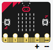
A microcontroller is a tiny computer that is designed to interact with electronic circuits through I/O (input/output) pins. We use the micro:bit in our example electronics projects but other microcontrollers can also be used. It's easiest to use one that has pads for connecting alligator cables.
¶ Cables (Wires)

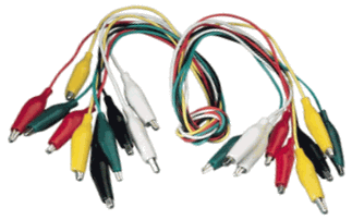
Conducting cables (wires) are used to connect the components of a circuit. Electricity can flow through the metal core of the cable, which is a conductor. Most wires are covered by an insulating plastic sleeve.
Alligator (or crocodile) cables are wires with metal clasps on either end that can be clamped onto components easily.
Alligator cables come in a variety of colors. Although their color has no effect on the circuit, a BLACK colored cable is often used for the Ground (GND or -) connection, and a RED cable is often used to connect to power (3V or +) connection.
¶ LED (Light Emitting Diode)

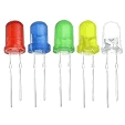
An LED lights up when electricity passes through it in the right direction. They are useful to provide visual feedback, for example, to show that a board or circuit has power. They are also artistically fun when used to make cool light-show circuits. The short leg of the LED (-) should be connected to the GND port.
¶ Resistor


A resistor restricts the flow of electricity in a circuit. They come in a variety of sizes. The higher the resistor value, the less current is able to flow. The colored stripes are coded to indicate the resistor value in Ohms (the unit of resistance).
¶ Potentiometer (Variable Resistor)

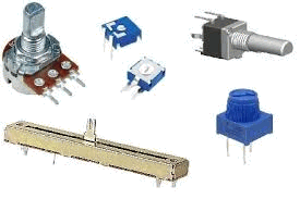
A potentiometer is a type of resistor whose resistance can be changed by the turn or sliding of a knob. The resistance value can be read by connecting the middle pin of the potentiometer as an analog input pin on the micro:bit.
¶ Piezo Speaker

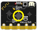
A piezo speaker is a sound output device. It can be controlled to make tones at different frequencies, thus enabling you to create music, alerts, or alarms. Some boards, like the micro:bit v2, have a built-in speaker for playing sounds. A set of old headphones or a small powered speaker can also be used for sound output.
¶ Batteries

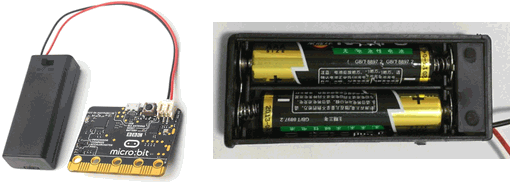
Two AAA or two AA batteries are usually used to power a micro:bit when it is not connected to your computer. Each battery is 1.5 volts. Together, they provide a total of 3 volts.
Batteries let you take your micro:bit creations with you in your pocket.
¶ Capacitor

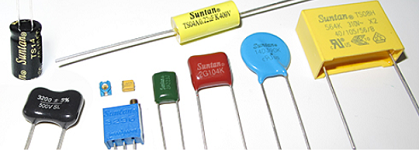
A capacitor stores and releases energy in an electrical circuit. You can think of a capacitor as a battery with very low capacity. You can charge and discharge it just like a battery, although unlike a battery a capacitor can only hold its charge for a short time. A capacitor is often used to introduce a time-delay in a circuit since it takes time to charge and discharge. Capacitors are also used for removing electrical noise and making the supply voltage of a circuit more steady.
¶ Multimeter

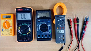
A multimeter is a tool for measuring voltage, current, or resistance in a circuit. It is a great tool for designing and debugging circuits. Is voltage applied? Is current flowing? Is the resistance across the circuit too high or too low?
You won't need a real multimeter for any of these projects. In some projects, you'll use your microcontroller to measure voltage or current just as you would with a multimeter.
¶ Connection Tips
The example projects described in the Electronics section of this wiki show symbols to represent the components that need to be connected to the micro:bit. For simplicity, the preferred method of connecting the external components will be to use one or more alligator cables.
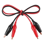
The cables have clips at both ends so they can be attached to micro:bit pins and to the wires or leads of the external components. For simplicity, project circuit diagrams don't show the ends of the alligator clips. Instead, they use colored lines or "wires" to represent alligator cable connections. For example:
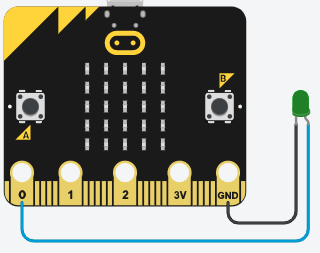
In the example circuit above, the positive leg of the LED is connected to pin 0 of the micro:bit (the blue wire), and the negative leg of the LED is connected to the GND (ground) pin of the micro:bit (the black wire).
A common circuit construction convention, and the convention used in these project diagrams, is to use a black colored cable between GND of the micro:bit and other components (such as the - end of an LED). However, you don't need to match the colors in the circuit diagram to your alligator cables; you can use whatever cable colors you want as long as they make the same connections.
A real-life version of the above diagram requires two alligator cables, and might look like this:
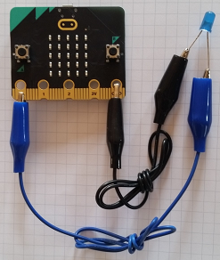
Sometimes you need to pay attention to the polarity (direction the electrical current is flowing), and other times you do not. In the example above, you do. The LED short leg (-) must be connected to the BLACK cable (ground), and the LED long leg (+) should be connected to the BLUE cable (pin 0). If the LED is connected in reverse, even when pin 0 is high (3V), current will not flow and the LED will not light.
¶ Multiple Components
When a circuit involves more than one component, you simply add as many alligator cables as required to make the connections. The number of different colored wires provide a hint of how many cables will be needed. In the following example, an LED and a resistor are connected in series between pin 0 and ground.
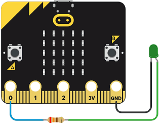
We already know that the polarity of an LED requires that its short leg (-) be connected to GND. What about a resistor? Resistors do not have a polarity requirement, so the cables can be connected to either end. We still have to follow the design of the diagram, but we don't have to worry about placing the resistor facing in one direction or another. Here is what this diagram might look like with real components:
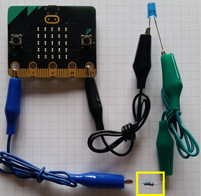
We have highlighted the resistor component in yellow, since it is so small and hard to see. An additional zoomed in picture shows its connections a bit better.
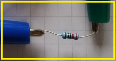
We have wrapped up the alligator cables so they fit nicely into these pictures, but you do not have to do that with your projects unless you want to.
¶ Safety
These electronics projects are powered by your microcontroller's 3V and GND pads on the gold-colored edge connector. The three volts (3V) from a microcontroller is safe in the sense that you can't get an electrical shock from touching it. (In contrast, the 120 to 240 volts from an electric power outlet can shock or injure. Stay away from that!)
To avoid damaging the microcontroller, never connect the 3V pad directly to the GND pad. That is called a short circuit and it allows a lot of current to flow, which can damage the microcontroller. (A momentary short circuit will probably not do any damage.) It is good practice to leave any necessary connections to the 3V pad for last and to double-check the other connections before making that final one.
Many of these projects use LEDs. When working with voltages higher than 3 volts (e.g. the 5 volts from a classic Arduino Uno), LEDs are used with a resistor to limit the current. However, when using LEDs with a 3V power source, one can omit the resistor, reducing the number of components and connections.
One last reminder is that some components have polarity, meaning that it matters which side of the component is connected to GND. When using such components, make sure that the positive (+) side of the component is connected to a wire that is coming from the 3V pad or one of the other micro:bit pins (either directly or through some other component), and that the negative (-) side of the component is connected to a wire that eventually leads to the GND pad. For example, if the polarity of an LED is reversed it will not glow. If your circuit looks correct but the LED is not lighting up as expected, check the polarity of your LED connections.
¶ Learning More
Øyvind Nydal Dahl's website build-electronic-circuits.com is a fantastic resource for learning about electronics. His explanations are easy to understand, and he focuses on the key concepts you need to build and understand circuits without getting bogged down in non-essential details and math.
If you get excited about electronics, his book Electronics for Kids is a great hands-on introduction to electronics for people of any age. I wish I'd had that book when I was first learning electronics.
Like Electronics for Kids, Make: Electronics is a practical, hands-on book that focuses on what you need to know to build your own circuits. However, it assumes the reader is ready to buy the necessary tools and parts needed to set up their own electronics workbench.