¶ Overview
Microcontrollers use input/output (I/O) pins to interact with the physical world. For example, the micro:bit's buttons are connected to input pins and its display is controlled by output pins. This project shows how to use an output pin to control an LED (light emitting diode).
With just a micro:bit or similar device, two alligator cables, and an LED, we can build this project in no time. After adding a bit of MicroBlocks code, we are ready to have fun turning the LED on and off by using the buttons on the micro:bit.
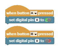
Here is a video of the finished project and the script that drives it:
 |
|---|
¶ Parts
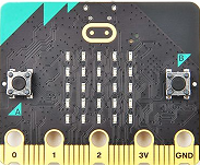
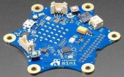
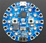
To start the project, collect the parts:
| a micro:bit | OR a compatible micro device | |
|---|---|---|
 |
 |
  |
-
a single-color LED (any color)
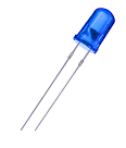
-
two alligator clip cables
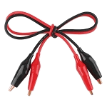
¶ Setup
-
Clip one alligator cable to pin-0 of the micro:bit and another to the ground pin (GND).
-
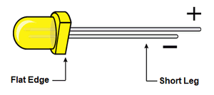
Check out the LED. It should have one short leg and a long leg. The short leg is used for the GND connection. The long leg is for the pin-0 connection.
If your LED has a flat edge, the leg closest to the flat edge is the GND connection.
-
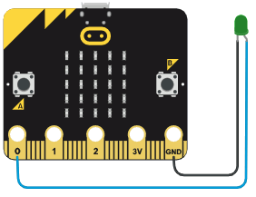
Now connect the cable clipped to pin-0 of the micro device to the long leg of the LED, and connect the cable clipped to the GND of the micro device to the short leg of the LED.
Here is a diagram showing the connections:
¶ Scripts

¶ Process
With the connections out of the way, we can focus on the code to turn on and off the LED.
Since we want the buttons A and B on the micro device turn the LED on and off respectively, we will need to use two button control blocks.
Button A control will turn the LED ON. Notice that we connected the long (+) leg of the LED to pin-0 of the micro device. That means, we need to control the LED using that pin.
Here is the MicroBlocks block we need (Pins category):

Notice that the pin is already set to 0, and the boolean slider is is set to TRUE (green).
When this block executes, MicroBlocks will set pin-0 to TRUE (HIGH) and make the LED turn on.
So far so good ! Now we can move on to Button B and the LED OFF code.
This is easy, because we just need to do the opposite of what we did with Button A. We will use the same block, but instead of setting it to TRUE (green), we will set it to FALSE (red).

When this block executes, MicroBlocks will set pin-0 to FALSE (LOW) and make the LED turn off.
To make MicroBlocks act and do something when we press a button, we need to use the WHEN BUTTON A pressed block (Control category).
Any action blocks we place under this block will be executed when the button press is detected. Since we have two buttons we need to code for, we will use the same block but with two different button selections: A and B.
The two scripts should look like this:

This code will turn the LED ON when Button A is pressed, and turn the LED OFF when Button B is pressed.
That's it! Test by pressing the A and B buttons to make the LED go ON and OFF.
¶ Discussion
A Light Emitting Diode (LED) is an electronic component that lights up when a current is passed through it. Most LED's are a single color, although some LED components combine several different colored LEDs into a single package. (Such LED's usually have more than two legs.) It’s easy to connect LEDs to the micro:bit with alligator leads, but it’s good to know a little bit about the electronic workings of theses devices before you start.
LEDs are diodes that emit light. A diode only allows current to flow in one direction. If the connections to the two legs are reversed, current won't flow and LED will not light up.
The micro:bit can switch the LED on or off by controlling the power to one of its output pins (e.g. pin-0) using the set digital pin block. An output pin is is like an electrical switch controlled by code.
The micro:bit power output is 3.3 volts. When a pin is set to HIGH, 3.3 volts are sent to the pin, powering the LED. When a pin is set to LOW, 0 volts is sent to the pin, turning the LED off.