¶ Introduction
MicroBlocks supports both I2C and SPI communications. In this writeup we will establish an I2C link from a micro:bit to an Arduino and communicate between them.
I2C uses just two cables and is very easy to set up. One cable SCL provides the clock signaling between the systems. The other SDA is used to transfer data in both directions.
Devices are designated either as Master or Slave, with Master controlling all the exchanges. In our project, micro:bit will be master and Arduino will be slave.
¶ Goal
You will follow the Setup instructions for cabling the two devices to establish a link between them and to power them. Then we will look at the coding required for both devices to implement the I2C protocol.
Following that, we will exchange some messages between micro:bit and Arduino.
¶ Materials needed
- BBC micro:bit and USB cable
- Arduino UNO and USB cable
- Some version of micro:bit breakout board
We used KEYESTUDIO KS0308 Motor Breakout Board
But many others that expose pins 19 and 20 of micro:bit will do just fine. - 3 x M/F jumper wires (20cm)
- LAPTOP with two USB ports
¶ Programs to download:
- For micro:bit: I2CToArduino MicroBlocks program
- For Arduino: microbit I2Cslave XMIT RECV
NOTE: It is assumed that the audience is familiar with the Arduino IDE use and loading programs onto the Arduino.
¶ Setup
Let’s look at how to cable the micro:bit and the Arduino systems to each other to establish the I2C connectivity.
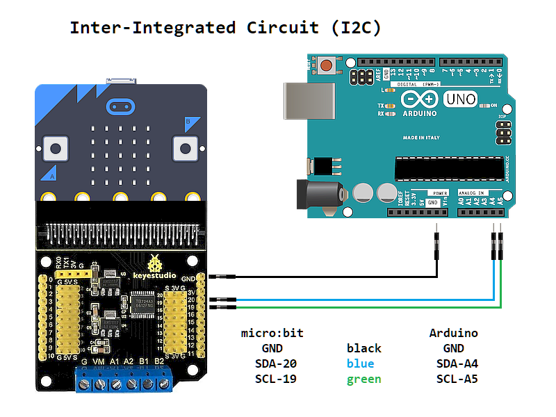
Important point:
Micro:bit and Arduino use different operating voltages, 3.3V and 5V respectively.
Please DO NOT directly connect these two to each other without a breakout board that provides voltage conversion.
In addition to the connectivity between the boards shown above, remember to use the respective USB cables to plug them into your LAPTOP or DESKTOP computer for programming.
¶ Procedure
For our project we will need two sets of programs: one for the micro:bit and one for the Arduino. Let’s look at both of them:
¶ Micro:bit Code
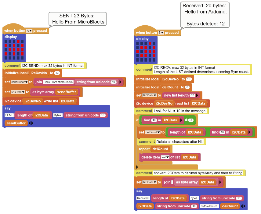
Micro:bit code is in two parts:
| - Button-A press code set enables you to SEND a message to the Arduino. - Button-B press code set enables you to RECEIVE a message from the Arduino. |
 |
|---|
Before we examine the code for these two functions, let’s review the I2C related coding blocks of the microBlocks IDE.
Following blocks make up the I2C functions:

This block reads the selected Register value of the selected I2C device. Value returned is a single byte integer in the range of 0 - 255.

This block writes a value to the selected Register of the selected I2C device. Value used must be a single byte integer in the range of 0 - 255.

This block enables us to read multiple bytes of data from the I2C device. The list length determines how many bytes will be exchanged. I2C has an internal limit of 32 bytes maximum. So only between 1 and 32 bytes can be exchanged via this block. The values in the list must be integer values in the range of 0 - 255. Anything else will be ignored.

This block enables us to write multiple bytes of data to the I2C device. The list length determines how many bytes will be exchanged. I2C has an internal limit of 32 bytes maximum. So only between 1 and 32 bytes can be exchanged via this block.The values in the list must be integer values in the range of 0 - 255. Anything else will be ignored.
For our project, we will only make use of only the last two list related blocks.
Let’s look at the code of these two functions in more detail.
Button-A SEND
So what we want to happen is, when we press the Button-A on the micro:bit, we want it to send out our message to the Arduino.
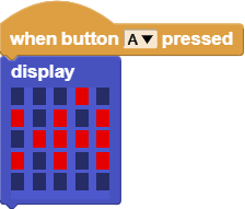
We start out with the Button-A pressed block and display a LED pattern of “> A “ to designate that the function is SENDING to ARDUINO.

In this part, we define our variables.
i2cDevNo is the I2C device number we have decided to use for the Arduino slave device. The selection is totally arbitrary, except that the first 0 - 7 device numbers are reserved by i2c. Anything 8 - 127 is OK.
sendBuffer variable is used to hold the message text we want to send to the Arduino device. In this example, I have created a 23 byte message. However, it could be up to 32 bytes.
I2CData variable is assigned the byteArray version of the sendBuffer content.
Since our message text is in a string variable sendBuffer, we have to convert it into the decimal bytes format required by the i2c write block.
Remember that I2C only likes integers between 0 - 255, and knows nothing about text letters or punctuation marks etc. That means, we have to take each and every letter of our message and convert it to a unicode ASCII value between 0 - 255. Then we have to store these one by one in consecutive locations of the variable I2CData. What better way to accomplish this than let microBlocks handle this laborious task.

Quickest way to convert the string data into decimal byte format is to use the as byte array block. This block does the conversion without resorting to loops that process each character.
Now it is in the proper format, ready to be sent out.

Here is where the action happens. We tell microBlocks to take our I2CData and send it to the i2cDevNo 13.
I2C library routines in the background will look at the I2CData variable length and calculate how many characters there are to be sent. Then the library will signal the Arduino that there are 23 bytes of data on its way, and send it out. Lots of activity happening in the background without our intervention or coding required. We have to thank MicroBlocks for making it this easy for us. Can’t say the same about the Arduino side though, as we will see in a bit.


And we finally reach the end of our SEND routine. Just to make sure everything before this point has been completed, we display a small message indicating the number of bytes we have sent.
Well, that wasn’t that bad at all! Other than a few variable setups and a small conversion from text to byteArray, we accomplished our I2C SENDing in one command block.
Now, let’s move on to the RECEIVING side of things.
Button-B RECEIVE
What we want to happen here is to receive a message from the Arduino, when we press the Button-B on the micro:bit.
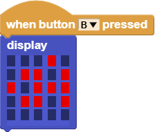
We start out with the Button-B pressed block and display a LED pattern of “< A“ to designate that the function is RECEIVING from ARDUINO.
Again, we have to define our variables.

i2cDevNo is our I2C device number that we will receive from.
I2CData needs to be setup as an empty list of 32 entries, ready to receive the Arduino message.

And the action block - we tell microBlocks to read multiple bytes from the Arduino device# 13 and place the incoming message into the I2CData variable. Again not much to do on our part, because of the helpful background handling of I2C details by MicroBlocks for us.
However, to appreciate it fully, let’s examine what goes on behind the curtain: The I2C library will initialize the I2C protocol details like speed, and designate itself as the master. Then it will look at the I2CData size and send a REQUEST message to the Arduino device #13 asking for 32 bytes of data. When that data arrives it will store it in the designated variable I2CData, and close down the I2C link.
We process the incoming data in two phases:
-
first we look to see if there are any NL characters (decimal value 10) in the message. As we have decided, we can send and receive 32 bytes of messages. However, if we want to send and receive less than that, then we need to add a NL character after the last good byte.
-
Second phase is to take the received decimal byte values and convert them to readable string version.
Let's see how we have written the code to do these things:
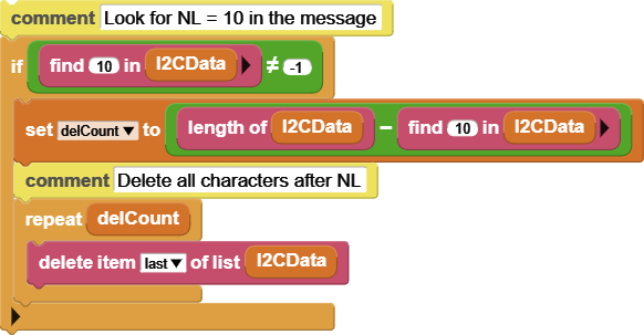
To begin with, our I2C data is waiting for us in the I2CData variable in integer format, all 23 bytes of them.
Let’s clarify some design decisions that were made (by me, of course) in order to ease the exchange between the systems.
As we have mentioned before, I2C data exchanges can be anywhere from 1 byte to 32 bytes. So to make our program a bit more flexible, in terms of how many bytes it can send and receive, I have decided to write the code for the 32 byte max length and handle the reception of shorter messages by placing a NEWLINE (NL) character at the end of the shorter messages originating in the Arduino. That way, by looking out for the NEWLINE character in the received message on the micro:bit side, we can tell that it is the end of it and quickly ignore the rest of the 32 bytes, if any.
Please note that this design decision is purely of my choosing, and it has nothing to do with the I2C operations, other than the 32 byte limit. One could just as easily operate on a byte by byte basis and handle the message exchange one character at a time. Or any number of bytes at a time. You decide for your own implementation.
Now that we know this, the code will make more sense.

The IF block, in combination with the find block, examines every byte of the I2CData and looks for the NL value. The NL byte has an ASCII decimal value of 10. So if it finds this in the bytes examined, it will return its location. If not found, it will return -1.
To check and see if we have found anything, we set the if block to execute if the condition is NOT EQUAL to -1, meaning there is a NL in the message.
When we find the NL, we do two things:
-
First, we calculate a local variable delCount and store in it the number of bytes left till the end of the buffer. In other words, since we know the location of the NL, we calculate how many extra bytes there are, if any. That is what the delCount variable stores. So anything after the NL is of no interest to us, and we’ll get rid of it.

-
Then we use a REPEAT loop with delCount as the parameter to delete all bytes in the rest of the I2CData. By using the DELETE LAST ITEM option on the list, we do not have to worry about where we are in the deletion process. We simply delete from the END of the list delCount times and finish our clean up. This leaves us with a clean list containing only the valid bytes of the incoming message.

Now that we have a cleaned buffer with nothing but the actual message characters in it, we need to convert the decimal byte values into more readable string format.

This task is very easy due to the help provided by Microblocks data manipulation blocks. as byte array block converts the list variable into a byteArray format. And then by using the join blocks with an empty first parameter, we force the entire byteArray to be converted to the string format.
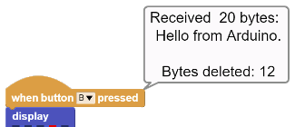
Here is a display of the program when the Button-B is pressed and the Arduino message is received:
OK, we have successfully reached the end of the micro:bit and MicroBlocks code.
Now we will look at the Arduino side of things.
¶ Arduino Code:
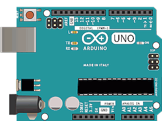
| The Arduino side of the code makes use of the standard WIRE library that is included with the Arduino IDE. Since the Arduino side is not a block based development environment, we don’t get to enjoy the many benefits of the microBlocks IDE that we came to like so much. |
 |
|---|
Again, as a design decision, I have decided to provide a program that will serve as both a SLAVE Receiver and SLAVE Transmitter. This will simplify things by making us work with only one program. In addition, as mentioned above, I had also decided to implement a 32 byte transmit / receive scheme. The main reason for that was to eliminate multiple code changes while testing the project. As far as the Arduino side is concerned, one only has to change the device # to match on both sides once. Then for any length of message exchange, there is only one string array to change on the Arduino side, and that’s it. Compile and Go !
Let’s look at the code:
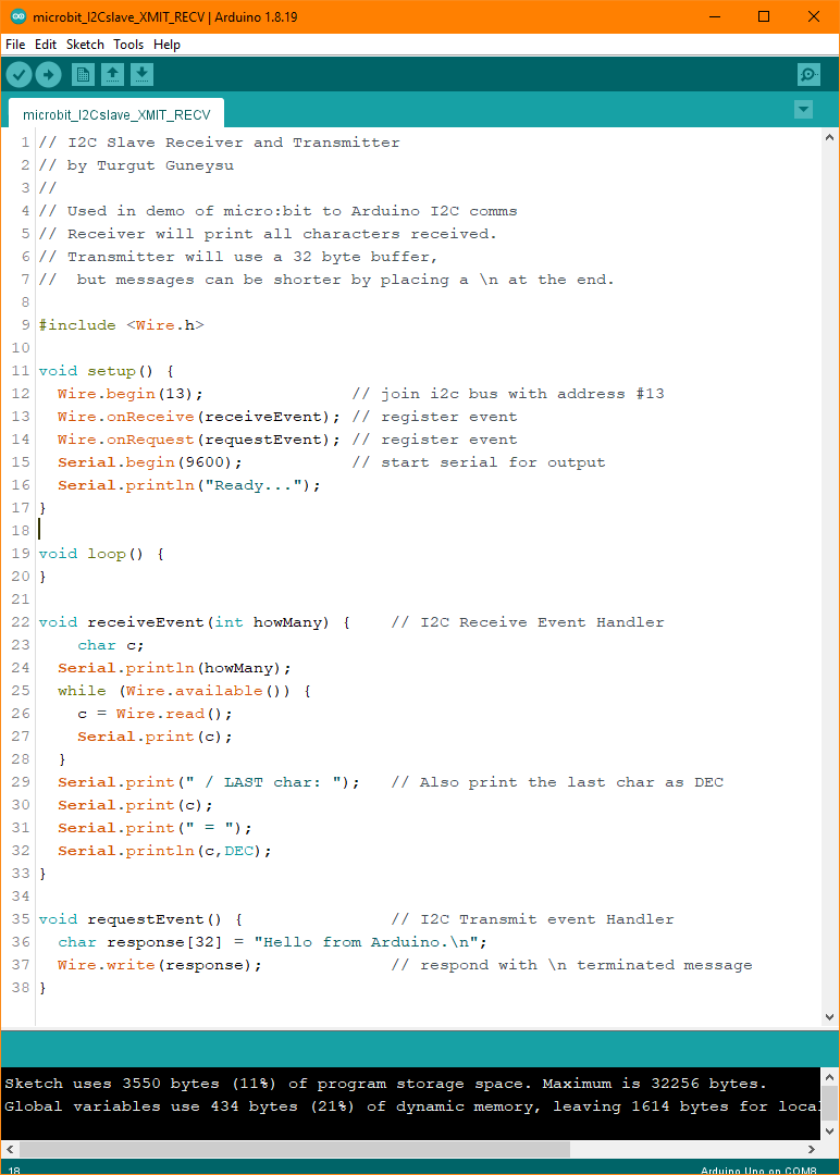
The Arduino program consists of the WIRE library include statement and four functions:
- <Wire.h>
This Library provides the I2C functionality - setup()
This is where the I2C WIRE library is initialized as device 13.
Two events are declared as functions to handle the RECEIVE and SEND events of the I2C.
Then the Serial port is opened at 9600 baud to enable program message display.
And a “Ready...” message is displayed on the Serial console. - loop()
This main loop of the program is not used, since the I2C events are interrupt driven and handled by the respective Receive and Request event handlers. - receiveEvent( int howMany )
This is the handler that processes the I2C messages received by the Arduino.
It displays the number of bytes received on the Serial console.
Incoming bytes are read from I2C using the Wire.read() function into the c variable
It prints every byte it receives on the Serial console
Additionally, it prints the very last byte in DECIMAL ASCII format just to make it easy to differentiate
any termination characters. - requestEvent()
This is the handler that sends out the designated message stored in the response[ ] array.
The message can be up to 32 bytes in length. If a shorter message is desired, just add a “\n” byte, which is the NEWLINE character to terminate the message.
The micro:bit side will look for this NEWLINE byte and ignore the rest of the buffer array.
The message is sent out using the Wire.write(response) function call.
As can be seen, there is much more coding to do on the Arduino side, albeit not that complicated. It makes one yearn for the simplicity of the microBlocks IDE.
Now that we have examined all project program codes, we can try to run things and look at the Arduino Serial Console display output.
ARDUINO Serial Console messages
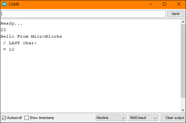
Since we are sending a 22 byte message from micro:bit to arduino, the end of the message is terminated by a NL character. This character is not a printable / visible character. It is imterpreted as a new line code. Therefore, in the console display, we see that the LAST char: has nothing shown next to, and the character code 10, which is NL, is printed on the next line.
¶ Comments
This project would be a good one for team-work. One group could focus on the micro:bit side, and the other on the Arduino. Also, each team could make design decisions regarding the I2C exchange and share with each other, as well as cooperatively implement them.
An interesting thought exercise would be how to enhance the programs to accommodate very large data exchanges.
Another interesting option is to write the code for single character transmissions and see if the execution time is heavily impacted.
Enjoy !