These notes are for advanced users who want to work with MicroBlocks on the NodeMCU and are comfortable with the extra technical challenges involved.
The NodeMCU is an inexpensive board based on the Espressif ESP8266 that includes a WiFi radio, 32-bit processor, nine digital I/O pins, and one analog input pin. The NodeMUC doesn't have many built in capabilities (just a user LED) so most interesting applications require connecting external components. The need for wiring makes the NodeMCU less appropriate for younger children and beginners than boards with more built-in features.
¶ NodeMCU Pins
MicroBlocks uses the digital pins marked D0 through D8 and the analog input pin marked A0 on most NodeMCU and other ESP8266 boards:

(Note: Early versions of MicroBlocks referred to pins using the ESP8266 GPIO pin numbers. However, in July 2020 it switched to using the Dx and Ax pin numbers printed on the board, which are more convenient. MicroBlocks programs for the NodeMCU written before that change will need to be updated to use those new pin numbers.)
For example, pin 0 is the top-right pin in the picture (D0). On many ESP8266 boards, that pin also toggles the user LED. On many ESP8266 boards, the sense of the user LED is inverted: setting the LED's pin to "false" turns the LED on. If pin 0 does not control an LED on your board, try the other digital pins. There are dozens of different ESP8266 boards and, unfortunately, they use a variety of pins for the user LED.
Most ESP8266 boards have two buttons. One of them, usually marked "RST", "Reset", or "EN", is the hardware reset button. The other button, usually marked "Flash", sometimes can be held down to force the chip into bootloader mode when installing firmware (not necessary on well-designed boards), but can also be used as "Button A" in MicroBlocks. It is connected to pin 3. That pin has a pull up resistor so it is high ("true" in MicroBlocks) when the button is NOT pressed and goes low ("false") when the button is pressed.
The Node MCU has a single analog input pin, marked "A0" on the board (top-left in the picture). That pin is analog input-only; it can't be used as an output.
¶ Serial Setup
On some systems, you may need to install a serial driver. Depending on the USB-serial chip on your board you may need one of these:
On Linux, add yourself to the "dialout" group by running this in a terminal:
sudo usermod -G dialout -a `whoami`
¶ Installing MicroBlocks Firmware
Here is a short video showing the firmware installation process.
https://youtu.be/DUCdC7c4dGg
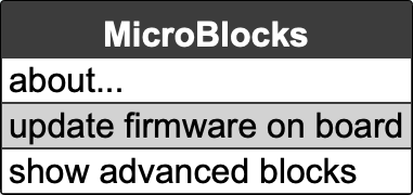
To install the MicroBlocks firmware on an ESP8266 board, launch MicroBlocks and plug in the board. From the MicroBlocks (gear) menu, select "install firmware on board":

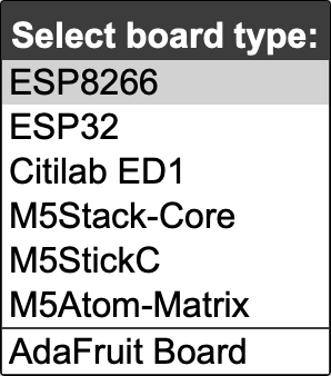
Then select "ESP8266":

If you have a specific board variant and you'd like to load its specific fimware image, you can first select "show advanced blocks" from the gear menu, and then select "install ESP firmware from URL". You will find some pre-built pilot firmware images on the MicroBlocks website:
https://microblocks.fun/downloads/pilot/vm/
(right-click one of the firmware filenames to copy its URL)
As the firmware loads, you will see a progress screen:

Once the firmware is installed, a green circle should appear to show that the board is connected.

That may take a few seconds. In rare cases you may need to disconnect and reconnect the board.
To verify that everything is working, try the following:

The LED on your board should light up, showing that the board is connected.
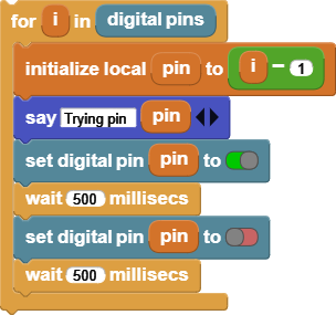
If the LED on your board does not light up, it could be that the LED is connected to a different pin on your board. You could look up the LED pin number in the data sheet for your board, but it's more fun to write a MicroBlocks program to find it for you:

You're ready to code!