¶ Overview
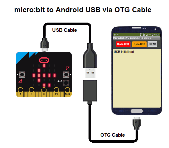
This document shows how to interact with a board programmed with MicroBlocks from Android App Inventor via a USB OTG cable. Using the library blocks presented here, App Inventor can request information from the MicroBlocks project, including the names and values of variables, the board type, and any messages that have been broadcast. It can also send information to the MicroBlocks project by changing the values of variables and sending it broadcasts. These features allows App Inventor to control a MicroBlocks project, display and log sensor data from MicroBlocks, or use MicroBlocks sensors to control an App Inventor game or other application.
Users familiar with the AI2 concepts can start working with the library blocks immediately by referring to this document.
¶ Summary of Blocks
¶ Connectivity and Information Flow
Our script, written in the Microblocks IDE, is loaded and running on the micro:bit device. Our APP, written in AI2, is loaded and running on the Android phone. Two devices are connected with an USB and OTG cable.
This setup facilitates programmatic communication to the VM code running in the micro device. This way, any App Inventor application can obtain a list of script variables running on the micro device, exercise read and write control over them, send and receive broadcast messages, and check the device type.
Using this feature will enable the user to treat the attached micro device as an extension of the Android phone and the other way around, as well as to fully integrate specific capabilities of both hardware with each other.
Since the communication is over a direct USB link operating at 115200 bps, the information exchange is very fast, and best of all, devoid of any memory size issues imposed by techniques such as WIFI or Bluetooth.
In a section below, we will review the blocks that make up the library services, and their usage details. But before we start describing the blocks, it is helpful to review the basic connectivity and the information flow between the AI2 and the micro device.
¶ VM to AI2 Connectivity
As shown in the picture above, the basic connectivity between the Android phone and the micro device is via an USB and OTG cable. Since both the phone and the micro device use their mini USB ports for connectivity, and these cables have USB A type ends at the other end, it is not possible to plug them into each other directly. The OTG cable simply permits one to do so. That's all to the connectivity from a hardware point of view.
Now let's look at the Android side from a software point of view.
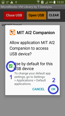
When a device is plugged into the USB port of the Android phone, it will ask the user for permission to use the USB port. This happens via a dialog box that pops up when the Android system detects the USB plug connection.
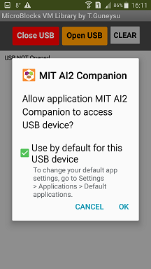
As can be seen, we need to place a checkmark into the box for default handler selection, and then click OK. This will get rid of the dialog display and establish a relationship between our program and the USB port.
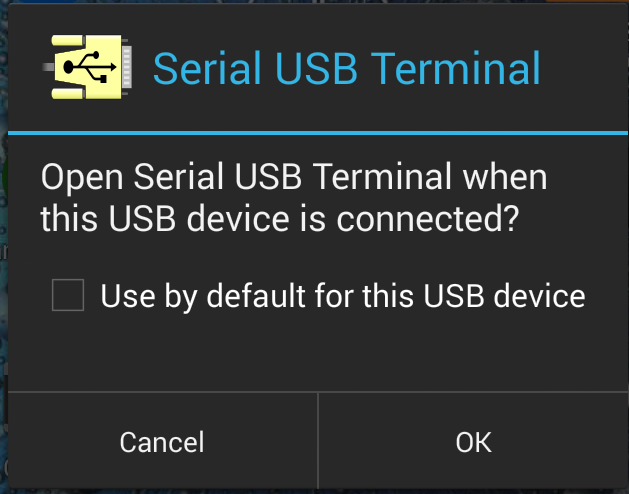
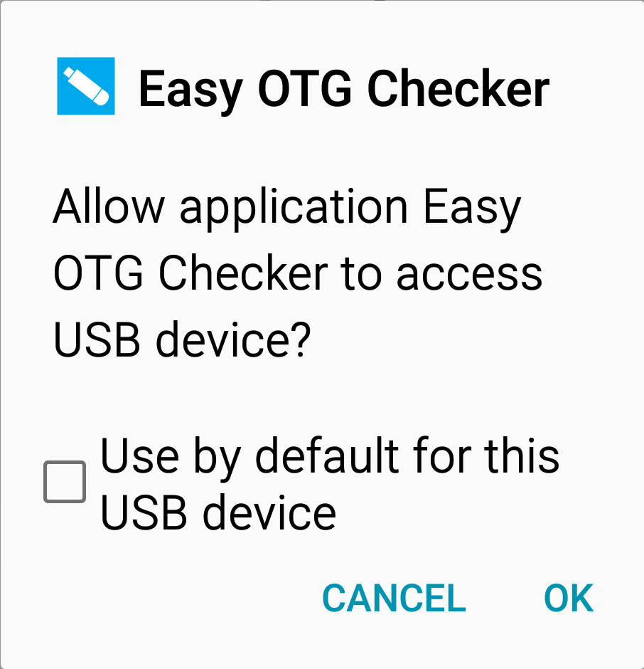
Sometimes, depending on how the Android systems are configured and what APPs the user has installed, additional dialogs might pop up, suggesting to use one of these other APPs to be the handler for the USB activity. We simply need to reject and discard these suggestions.
Android phones use the USB port on the phone for various purposes: charging the battery, media exchange with outside devices, backup and restore operations, etc. To support each one of these use cases, various Android APPs are designated as the handler. Therefore, when the Android system sees something getting plugged into its USB port, it will do two things:
- It will ask for permission to use the USB port facilities
- And it will automatically execute the appropriate handler APP to take care of the service to be delivered.
This is all fine, except that in our case, we want the APP that we have written and its libraries to be the designated handler, and not one of the other default Android APPs.
However, since we are not doing the Android APP development using the actual Android APK, we have no way of establishing and controlling this relationship programmatically in a permanent way. Therefore, every time we disconnect and connect the USB cable to the phone, we need to go through the process of:
- Giving our APP the permission to use the USB port,
- And assigning the port services to the MIT AI2 program we have written,
- And occasionally, reject the suggested Android APP handler program.
¶ VM to AI2 Information Flow
The AI2 APP that we will develop works as an event-driven single threaded program, operating in an asynch manner. What this means is that any and all programmatic activity with the outside devices started in an APP has to go through two phases to complete.
- The first phase is the information request phase. This is when we tell the outside device we are communicating with, what we want done.
- The second phase is the information return phase, sometimes also referred to as the callback stage. Here, the device we are communicating with has completed the task we have asked it to do, and returns us any info, if there is any.
The critical information to keep in mind is this:
- While we are in charge of phase one activity (we start it with our command issued to the micro device), we DO NOT control the response phase in any way. It happens when the device is ready. And this is what is meant by the term asynch used above.
- Therefore we have to provide our code that handles the responses and wait until the phase two activity is initiated by an event. This happens when the Serial port reports that there is information to be received from the micro device.
This back and forth communication model is very crucial to understand and for the programming activities to make sense. A typical example for this type of activity is when we ask for the value of a variable. We send out our request, and then a bit later a response arrives delivering the value of the variable.
Also good to keep in mind is that not all requests to the outside device will generate a response. Sometimes, we just tell it to do something and it does it. There is no need to respond back. An example of this would be setting the value of a variable. We tell it to set any variable to any value, and it gets done. Nothing to report back.
There is one final mode of activity that we need to know about: These are messages that arrive from the micro device without us asking it to do so. In general, these will be broadcast messages issued by our MicroBlocks program that we have running in the micro device. We will look into how to handle these messages when we review the example APP operations.
Now that we know how to link our APP to the USB port as a handler and we understand a bit what the information flow looks like, we can start looking into the details of the library blocks.
¶ Library Blocks
The library consists of a set of simple services, that together allow the user to have complete control of the variables and broadcast messaging facilities of the micro device.
¶ VM_Get_VarNames
¶ VM_Got_VarNames


These blocks are used to obtain a list of the variables names of the MicroBlocks program running in the micro device. It fits the two phase exchange model described above. The VM_Get_VarNames block requests the information, and it calls the VM_Got_VarNames block when the information arrives.

The variable names received are placed into a dictionary data structure to facilitate the library usage. The name of this dictionary variable is VM_varNames. The block above shows how the APP would initialize the dictionary. With the help of the dictionary, we are able to use all the library commands by referring to the actual names of the variables, instead of the encoded ID's.
Since MicroBlocks program variable names do not constantly change, we usually have to use these blocks just once when we first start our interaction with the micro device.
The dictionary that is generated contains key:value data pairs, where keys are the variable names, and the values are the variable ID numbers used by the program internally. This associative relationship allows us to only use descriptive variable names with the library commands.
The block segment pictured below shows how the VM_Got_VarNames block is used to display the names of the variables on the phone display.
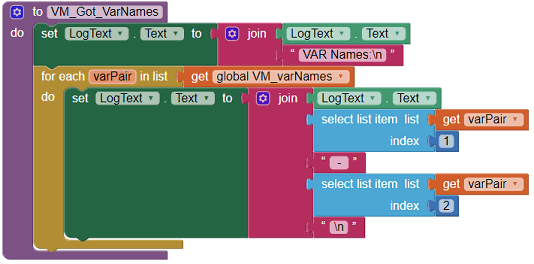
And this is the resulting display on the Android screen.
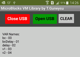
¶ VM_BoardType
¶ VM_Got_Board


These pair of BoardType blocks enable us to query the type of device we are communicating with. Since different devices have different characteristics and specifications, this information is helpful for us to customize the APP accordingly.
As with the VM_Get_VarNames above, this is a two phase command and delivers its results in the corresponding VM_Got_Board block. We simply need to code whatever we want done with the info returned into this block.
VM_Got_Board block has a parameter called boardname. This is set to the board type of the connected micro device. It can be accessed by the standard AI2 conventions of get / set blocks displayed when the mouse is placed over it:

Since this is also a type of info that does not change throughout the interaction with the micro device, it might be useful to save the board type into an APP variable, to be used whenever needed.
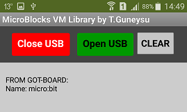
The block segment pictured below shows how the VM_Got_Board block is used to display the board type on the phone display.

And this is the resulting display on the Android screen.
¶ VM_Broadcast

The broadcast command is a dual purpose command. It can be used by the AI2 APP to signal intentions to the MicroBlocks program running on the micro device, as well as by the micro device to send programmed broadcast messages to the AI2 APP. It is also representative of a one way command described above. We issue it and there is no reply phase. Or the micro device issues it and it arrives unannounced.
This block has a parameter msgString that needs to be provided as the message text that will be sent out.
In the example use shown below, we send out a message "start Motor" to the micro device. It will receive this message via a MicroBlocks script block when start Motor received running in the micro device.


¶ VM_Get_Broadcasts

As was mentioned above with the broadcast command, broadcast messages originating in the micro device can arrive totally unannounced in the Android APP. The Serial Read and the Parse Response streams of the library blocks are coded to handle these incoming broadcast messages and place them into a message queue called VM_broadcasts.

The broadcast queue is a list of n elements and operates in an FIFO (first in, first out) fashion. The queue size is controlled by the BC_Queue_Size variable. It can be set to any number of messages appropriate for the APP being developed.

As broadcast messages arrive from the micro device, they are added to the queue. When the VM_Get_Broadcasts command is used, it will retrieve all the messages in the queue and deliver them to the APP in the sequence they were received. Upon delivery, the message queue will be cleared out to prevent duplication of messages. It is the APP's responsibility to periodically check the broadcast queue and process the messages received.
If the queue is filled with incoming messages, and a new one arrives, then the first element of the list (the oldest message) will be deleted and the new message added to the end of the list. Since this action will in fact cause the unprocessed messages to be lost, it is important to size the queue properly and to process the messages frequently, to prevent losses.
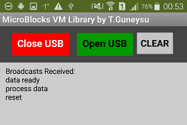
The block segment pictured below shows how the VM_Get_Broadcasts block is used to retrieve and display the messages received on the phone display.
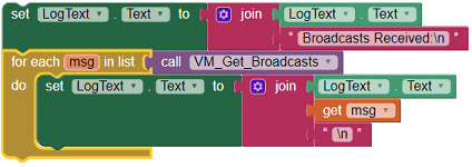
And this is the resulting display on the Android screen.
Don't forget:
Every time this block is used, the message queue is erased.
¶ VM_Get_Var
¶ VM_Got_Var


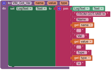
Here we have a two phase command to retrieve variable values from the script running in the micro device. VM_Get_Var sends out the request for a particular variable, and the VM_Got_Var is executed when the response arrives.
Note that the VM_Get_Var has a parameter that needs to be set to the name of the variable whose value we want to get. Remember that VM_Get_VarNames mentioned in the beginning of this section is used to obtain the names of the variables.
VM_Got_Var block provides us with three pieces of information for each variable: its name, value, and the type of the variable. The variable types are 01-Integer, 02-String, and 03-Boolean. As described in the VM_Got_Board block above, the three pieces of information can be obtained by moving the mouse onto the desired parameter and using the standard get-option from the menu.
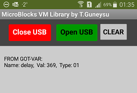
The block segment pictured below shows how the VM_Got_Var block is used to display the value of the variable named delay on the phone display.
And this is the resulting display on the Android screen.
¶ VM_Set_Var

This command enables us to set the value of a variable in a script running on the micro device. It is a one-way command with no reply.
The block requires two parameters: variable name and variable value.
We already covered the variable name above.
The variable value can be specified three different ways. Selection of one of these three value blocks on the APP side automatically determines the variable type setting on the MicroBlocks side.
 As an Integer, the value can be declared using the math number block.
 As a String, the value can be declared using the text block.
 As a Boolean, the value can be declared using the logic true/false block.
This will make the variable on the micro device side to be set to MicroBlocks  blocks.
¶ Setup
NOTE:
It is assumed that the user is familiar with the APP Inventor setup and use. For details, please refer to MIT AppInventor Documentation.
The library blocks are presented in an AI2 program file, together with minimal User Interface components, to make it easier for the user to start exploring.
Also provided is a small MicroBlocks program that will help the user test the initial interaction between the Android phone and the micro:bit device.
¶ Hardware You Will Need
micro device (micro:bit or similar kind)
ANDROID Phone with Android version 5 or above (v6 preferred)
USB cable
OTG cable
¶ Download Program Files
The App Inventor program file containing the library blocks can be downloaded here: MicroBlocksVMLib.aia
The MicroBlocks program can be downloaded here: VMTest.ubp
¶ Prepare Your Environment
Since we are creating a communication link between the MicroBlocks running in the Windows environment and the App Inventor APP running in the Android world, let's review setups for both sides.
¶ MicroBlocks Side
- Run either the Standalone or the Browser version of the MicroBlocks IDE.
- Load the MicroBlocks program you have downloaded into the IDE.
- Connect a suitable micro device of your choosing with a USB cable to the PC where MicroBlocks IDE is running.
- Enable the USB connection by clicking on the USB icon and making sure it turns green:

- Click the Run icon and observe the display on the micro device. It should be as shown in the video below:
If you see the letter F with the flashing User-LED on the micro device, you can proceed to the setup of the Android Side.
¶ Android Side
-
Run the App Inventor IDE and load the project file you have downloaded.
-
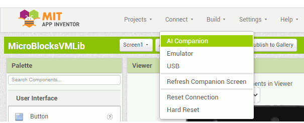
Establish a WIFI connection to the Companion APP running on your phone by selecting "Connect/AI Companion", as shown below:
-
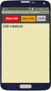
You should see the phone display the APP screen as shown below:
¶ Connect the micro device to the Android Phone
At this point, you can disconnect the micro device from the PC and, if you wish, terminate the MicroBlocks IDE.
Using the USB and OTG cables, connect the micro device and the Phone. It should be close to the picture shown below:

Please note that the cabling shown in the picture might not be exactly how your devices need to connect. This is due to the differences in various phones' USB ports and actual cables that might be required.
When the cabling is completed, the USB cable will provide the power needed to run the micro device, and you should see it come on and display the letter F with the flashing User LED, as described earlier.
Throughout this process, your phone's WIFI connectivity to the APP Inventor IDE should still be in place and operational. Just in case, due to any timeouts, if the link is broken, repeat the AI2 connectivity steps described above and establish the link to the Companion APP.
If all is well so far, we are ready to proceed to the testing of the interaction between the devices.
¶ Testing the Setup
First thing we need to do is to establish the USB connectivity between the micro device and our APP running in the phone. At this point, it might be helpful to review the process described in section VM to AI2 Connectivity above.
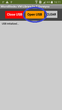
We start by clicking the "Open USB" button at the top of the phone screen.
This will cause the Android OS to display the USB permission screen. As described in the reviewed section above, we checkmark the "Use by default by this USB device" selection and click OK.
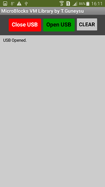
The Android permission screen display will go away and we will be returned back to our APP screen. Now that we have given permission to the USB port access, we will click the "Open USB" button one more time. This time it should turn green and the message "USB Opened" should be displayed in the display area of our APP.
Here are the screen sequences for the interaction described so far:
With the green "Open USB" button indicating we have a good connection to the micro device, we can start the information exchange between the devices.
On the micro device, press the Button-B. This will initiate three broadcast messages to the Android phone. They will be processed and displayed on the screen, as shown below:
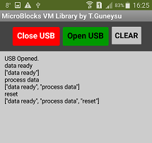
All incoming broadcast messages are stored in a message queue. Here we see the incoming broadcast message displayed, followed by the contents of the message queue displayed in AI2 list format (within squared brackets).
If you have followed and gotten the same results described here, we have shown that inbound communication is working fine.
Now, it is time to test the outbound communication.
On the AI2 IDE screen, click the "Blocks" button at the top right of the screen.
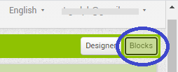
This will switch the IDE to the blocks display mode, and enable us to see the library blocks provided. The picture below is a zoomed out version of all the blocks in the program. It is meant to orient you to easily locate the block we need. Remember to use the AI2 zoom controls at the bottom right of the page to help you navigate.
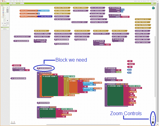

Try to locate the block circled in BLUE towards the middle of the display. It should be the "call VM_Get_VarNames" block:

This is the block we will use to obtain a list of the program variable names from the micro device.
With mouse over it, right click and select "Do It" from the menu.
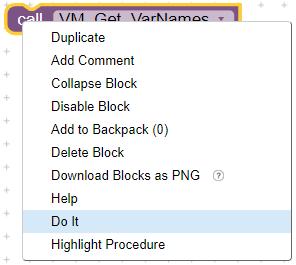
You should see on the phone display a list of variables names sent from the micro device, listed right after the last set of broadcast messages we had received:
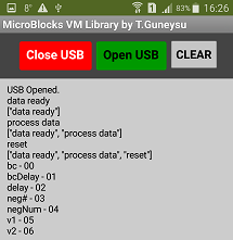
There it is ! We have tested both inbound and outbound connectivity between our devices. Messages were exchanged and displayed on the phone screen.
Now that everything is working OK, you can proceed to experimenting with all the other commands described above.
¶ Tips on working with the USB Port
During development and testing, one has the need to switch between the test setup of:
- the phone connected to the micro device and
- micro device connected to the PC's USB port and the MicroBlocks IDE.
If this is done without following proper steps, it results in needing to restart the Companion execution on the Phone, and similarly possible restarts of the AI2 Editor as well.
Here are a few points to be aware of:
¶ Timeouts
AI2 editor sessions are subject to inactivity timeouts.
So, after you switch to the MicroBlocks IDE, and while you are busily editing your micro device program towards perfection, if too much time has passed, your AI2 session will expire. And when you return and start making changes in the AI2 IDE, you will be greated by the message that says you have to refresh your session. No harm done but annoying ! So just to be sure, save and export your project before switching contexts to avoid any nasty surprises later on.
¶ Port Use Conflicts
There is only one USB port on the phone, and it is subject to Android OS intervention every time there is a disconnect / connect of any sorts.
So when you are testing the Android sections of your code, and you have the need to switch to the MicroBlocks IDE for some micro device enhancements, try to follow the procedure below:
-
Before you disconnect the USB cable, make sure you click on the "Close USB" button on your phone APP. This will release the USB port in the Android side and will stop the Serial extension in the AI2 from polling the port for data.
-
Similarly, when you are done with the MicroBlocks IDE side, "disconnect the USB" by clicking on the USB icon making it switch to non green status.
-
When you return to the AI2 IDE, first plug your micro device to the USB / OTG cable and then click on the "Open USB" button on the APP. If all is well, you should either see an immediate green status with "USB connected' message, or the display of the "USB Permission" screen. Both of these are good outcomes and will allow you to proceed normally.
-
Sometimes, the above process results in a display of "USB not opened" messages on the Phone. This is an indication that AI2 Serial extension and the Companion APP is out of synch, and one needs to terminate and restart the Companion.
¶ Android Side USB Interactions
Phone USB port is subject to monitoring for connect / disconnect activity by the Android OS. Now is a good time to review the description provided in section VM to AI2 Connectivity.
As described there, the phone environment might have various APPs that are designated as the handlers of USB related services: media up and downloads, system backups, external storage device use, etc. Each one of these APPs, at install time, will request and obtain access permission to the USB port, amongst other permissions.
Then when there is a connect / disconnect type activity on the port, the Android OS will determine what type of device is being connected and start running the handler APP it thinks is right. This will result in screen display of various APPs popping up and asking to use the port.
If you encounter this type of activity during your testing, simply ignore them and make sure NOT to OK the request. The annoying part is that this selection process is NOT a permanent setting, and wil occur again and again later.
One drastic but sometimes necessary method of handling these messages is to go ahead and either uninstall the said APP or, if possible, disable it. This topic is beyond our scope here, and should be researched via Android help resources.
NOTE:
If the APPs in question are part of the Android OS Services, then it will not be possible to uninstall or disable them. eg.: File browsers.
¶ AI2 Related Changes
This item has indirect impact on the USB connectivity, but it is an important point to keep in mind.
While working in the AI2 IDE, there are many changes that can be done interactively and tested without interruptions to the USB connectivity.
However, if any changes are made that:
- impact the screen layout,
- modify used extensions
- change the properties of the GUI components
then AI2 will refresh the screen display, restart the APP, and consequently disrupt the existing USB connection.
If this happens, you will have to restart the Companion APP on the phone.
Sometimes, it is helpful to click the "Close USB" button before attempting any of the changes above. This way, when the APP is refreshed and restarted, the "Open USB" will have a clean start and may prevent any unnecessary Companion restarts.
¶ User selected AI2 Refresh
You will from time to time have the need to restart your APP while working in the AI2 IDE.
The safe way to do this is:
-
Click the "Close USB" button and make sure the "Open USB" turns yellow.
-
Click on the AI2 menu item Connect / Refresh Companion Screen.
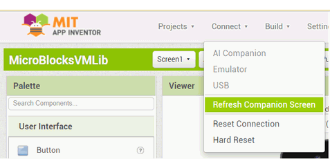
-
After the APP is restarted and you see the "USB Initialized" message, click on the "Open USB" and make sure it turns green.
Following these steps will ensure a more controlled development cycle with less frustrations.