MicroBlocks runs on over eighty microcontroller boards (and counting!). Support for these boards falls into three categories: selected boards for education whose firmware is built into the MicroBlock editor, boards whose firmware can be installed easily from the MicroBlocks website, and boards for advanced users willing to compile the firmware themselves.
Additional technical information about many boards (e.g., special purpose pins) can be found here.
¶ Boards for Education (Built-in)
The MicroBlocks firmware for these boards is built in, and can be installed directly from the MicroBlocks editor.
These boards are designed for beginners with no prior experience with microcontrollers and are widely used in schools and maker spaces around the world. The MicroBlocks firmware for these boards is fully supported and regularly tested by the MicroBlocks team.
Pre-built MicroBlocks firmware for several other educational boards is available for download.
¶ BBC micro:bit ($18)
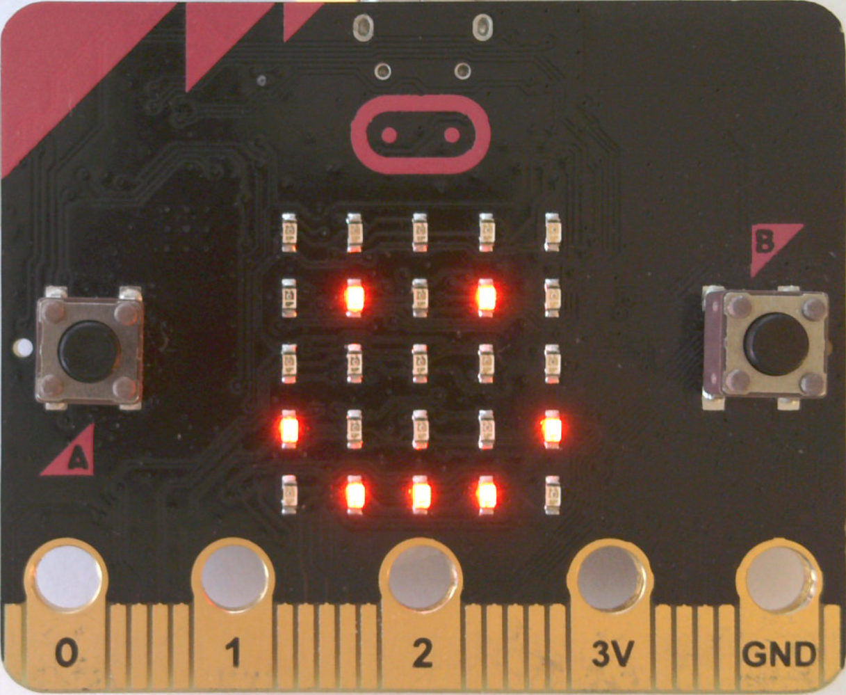
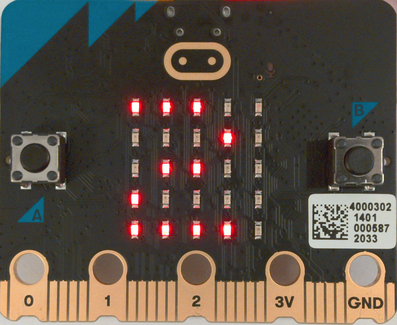
The micro:bit is one of the most popular microcontroller boards for education. Over five million micro:bits have been distributed in over sixty countries (ACM 2020) and the micro:bit Educational Foundation reported that over twenty million students have used micro:bits as of 2019. That number is higher now.
The micro:bit has a rich set of features, including two buttons, a 5x5 LED array that can display graphics and text, a radio that supports peer-to-peer messaging, and sensors for light, motion, and temperature. The micro:bit also has an edge connector that allows additional devices to be connected if desired, but adding components is not necessary. The many built in features of the micro:bit allow beginners to do interesting things immediately without wiring. That simplicity allows the micro:bit to be used by elementary school children (grades 3-5) as well as teens and adults. The micro:bit has a low floor and a high ceiling.
MicroBlocks supports both the original micro:bit and the new micro:bit v2, which adds a speaker, microphone, touch sensor, and other improvements to the original design.
Note: The micro:bit v1 does not support Bluetooth Low Energy. Due to memory limitations, some software that runs on the micro:bit v2 may not work on the micro:bit v1.
¶ Calliope mini ($50)
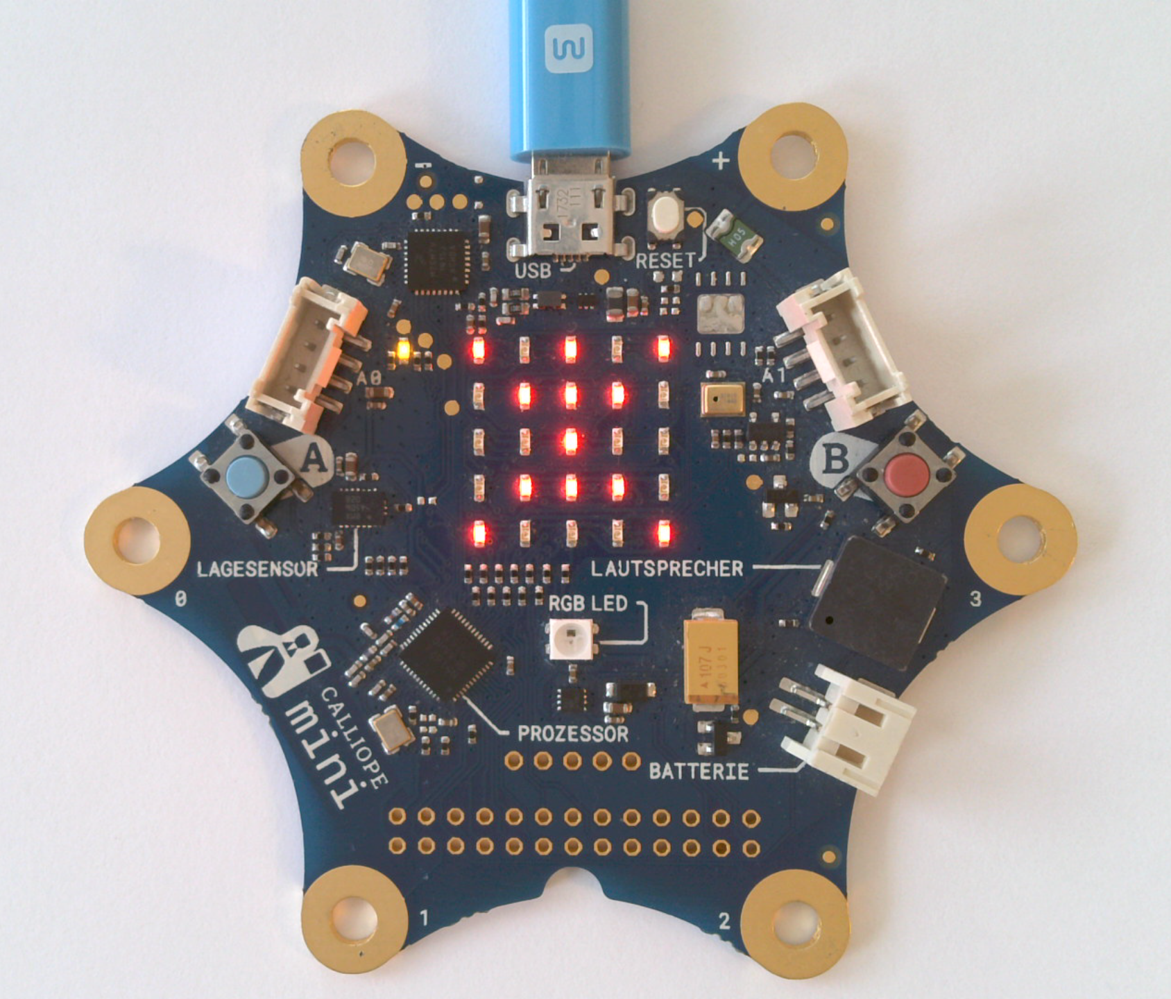
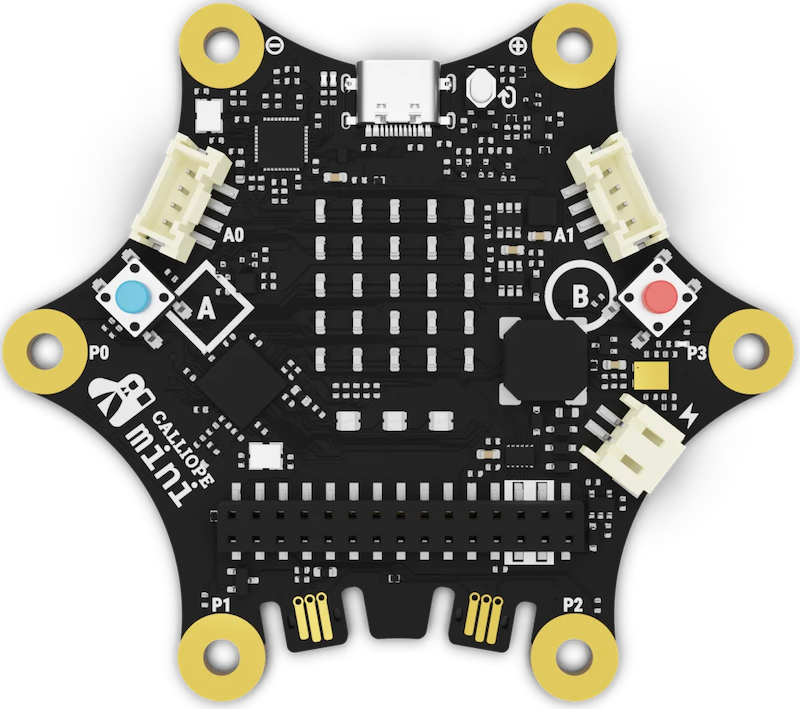
The Calliope mini is a German variant of the micro:bit, with a few changes and extensions. The most obvious change is the shape of the board, which was optimized for use with alligator clips. The Calliope mini also has a built-in speaker, a microphone, and an RGB LED. While it lacks the micro:bit's edge connector, it has two Grove connectors for connecting additional components.
In the US, the Calliope mini is available from Adafruit.
MicroBlocks supports both the original Calliope mini (v1 and v 1.3) and the Calliope mini V3.
Note: The Calliope mini v1 and v1.3 do not support Bluetooth Low Energy. Due to memory limitations, some software that runs on the Calliope mini V3 may not work on the earlier versions.
¶ Citilab ED1 (€38.50-€45.00)
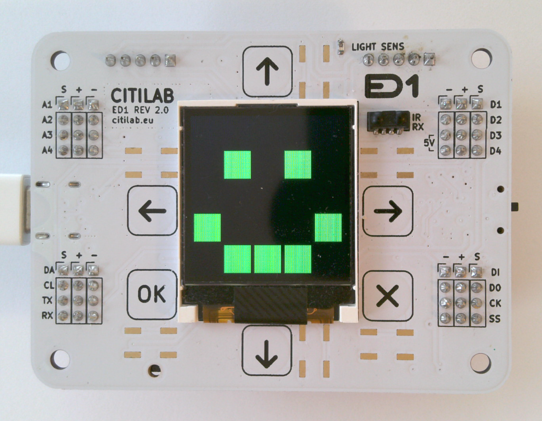
The ED1 board and the related robot kit were developed by the Citilab Cornellà EduLab specifically for K-12 education. EduLab has led workshops for thousands of school children using MicroBlocks on the ED1.
Over the past several years, the ED1 board and robot kit have gone through multiple design-and-test cycles, and it shows. Their robot uses stepper motors (the motor controller is built into the board) for precision. As a result, it can turn and move by exact amounts and, when dragging a pen, is capable of drawing geometric figures accurately.
The ED1 has a 128x128 color display that can be used to display text and graphics. There is even a Logo Turtle library for it. The display can simulate the micro:bit's 5x5 LED display, so the ED1 can run micro:bit programs. The board includes a nice built-in speaker, six touch buttons, motion, light, and temperature sensors, an IR receiver, and a set of GPIO pins for connecting additional devices.
Finally, the ED1 supports WiFi. Using MicroBlocks libraries, you can create a simple HTTP server that you can use to remotely control the ED1 from a web browser or from a Snap! program.
¶ CoCube
CoCube €90 (expected $100-$115)

The CoCube in a tiny "table-top robot" designed to operate in the small amount of desk space next to the user's computer. It has a color display, buzzer, two buttons, rechargable battery, wireless operation, and a port for accessories such as a gripper.
However, what really sets the CoCube apart is a novel optical sensing system that allows it to detect its position and orientation when operating on special optically encoded mats. This feature allows precise absolute positioning which supports math education (e.g. learning about Cartesian coordinates and angles) as well as fun, multi-robot activities such as robotic soccer.
The CoCube recently became available for sale in the EU and is expected to become available in the US for a little over $100, depending in part on tariffs.
¶ KidsIOT
KidsIOT $16

The KidsIOT board has wireless capabilities, a 128x64 monochrome OLED display, two servo ports, and nine jacks for external modules. The color-coded modules are connected using modular cables that are reliable and easy to use. Support for the KidsIOT board and its modules is provided by the MicroBlocks KidsIOT library.
¶ Foxbit
Foxbit $15

The Foxbit board features two buttons, a 7x5 RGB LED array, a speaker, wireless support (WiFi and Bluetooth), an accelerometer, and sensors for light, sound, temperature and humidity. In addition, it has a micro:bit compatible edge connector so it can be used with robots and other peripherals designed for use with the micro:bit.
¶ micro:STEAMaker
micro:STEAMaker €26

The micro:STEAMaker board features two buttons, a 5x5 RGB LED array, a speaker, wireless support (WiFi and Bluetooth), a six-axis accelerometer/gyro, and sensors for light, sound, and temperature. In addition, it has a micro:bit compatible edge connector so it can be used with robots and other peripherals design for use with the micro:bit.
¶ Circuit Playground Express and Bluefruit ($25)
Circuit Playground Express Circuit Playground Bluefruit
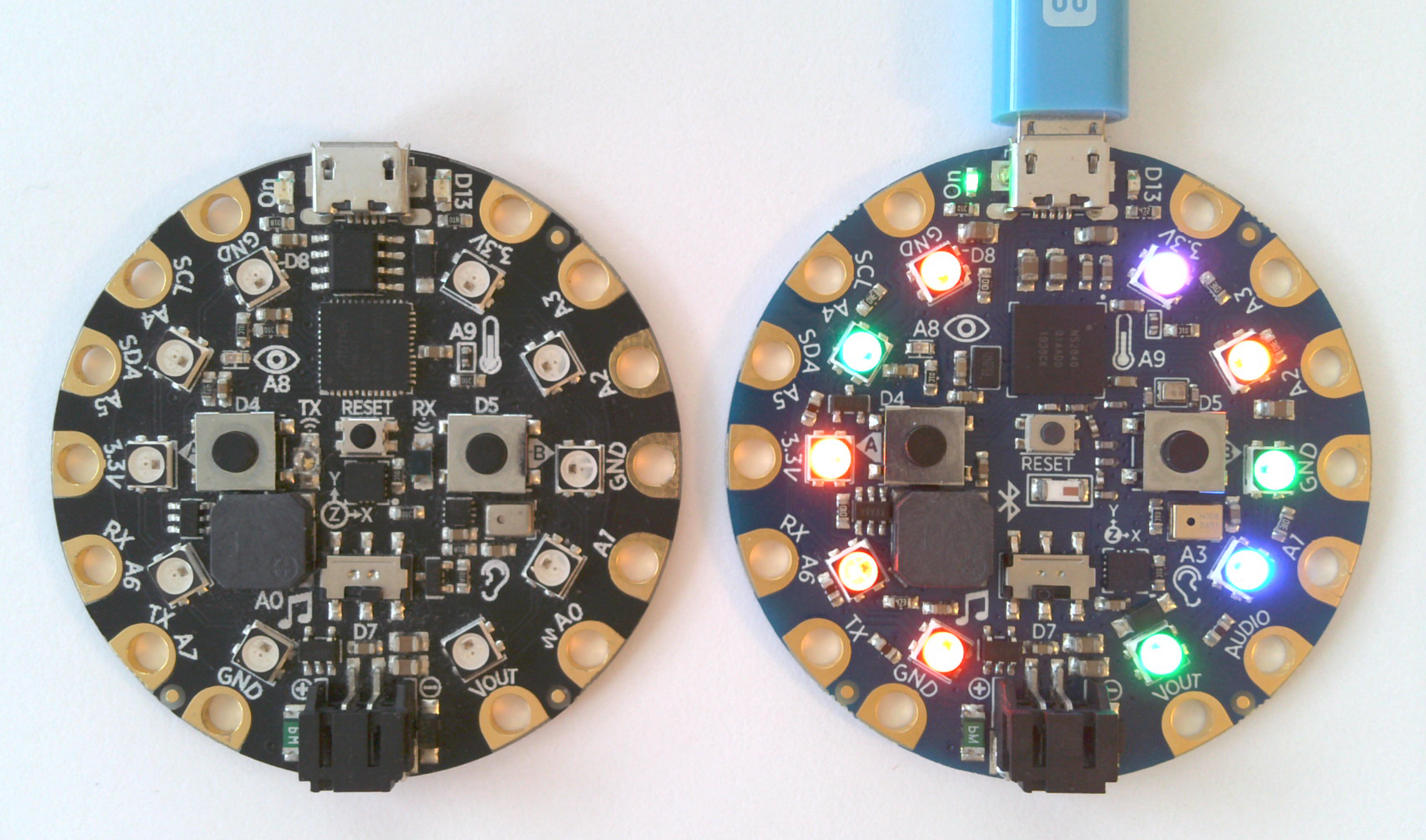
The Adafruit Circuit Playground Express and Circuit Playground Bluefruit are also popular with educators. These boards feature a set of buttons and sensors similar to those of the micro:bit, but replace the 5x5 LED display with a circle of 10 programmable RGB LED "NeoPixels" than can be used to create colorful, eye-catching animations. These boards also have good built-in speakers and eight alligator-clip friendly GPIO pins. Less obviously, these boards have beefy power supplies that can drive multiple external devices such as servo motors or NeoPixels strips. THat makes these boards especially useful in art projects.
The Circuit Playground Bluefruit (but not the Express) has a radio that can communicate with the micro:bit and Calliope mini.
¶ Raspberry Pi Pico 1 and Pico 1 W (RP2040) ($4, $6)
Raspberry Pi Pico and Pico W (RP2040)
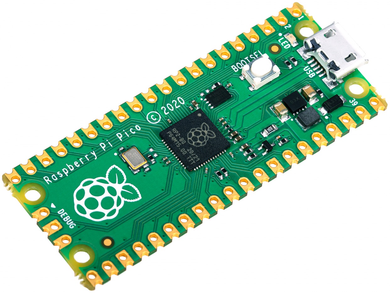
The $4 Raspberry Pi Pico RP2040 module is bare-bones: the only built-in peripheral is a user-LED. But because it provides a powerful processor at an extremely low price, this module forms the core of many other boards that provide a wide range of peripherals and functionality. One example is the PicoBricks board from Robotistan.
The $6 Pico 1 W includes a combination WiFi and Bluetooth chip.
¶ ESP8266 ($4) and ESP32 ($8)
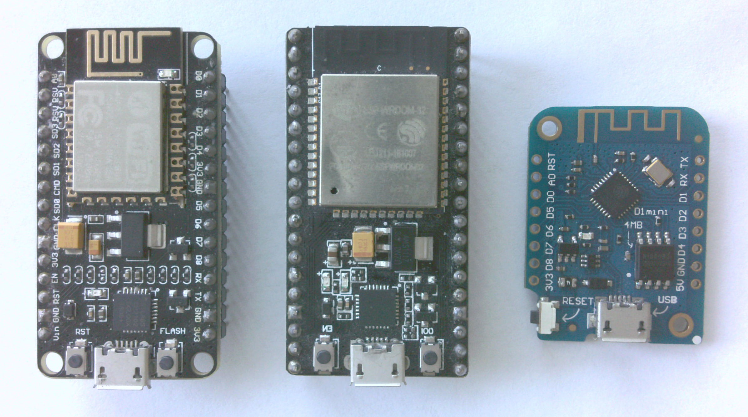
Created by the Chinese company Espressif, the ESP8266 and ESP32 are WiFi-enabled microcontroller modules used by the WiFi-capable boards listed above. But ESP modules are also available as inexpensive bare-bones boards designed for electronics hobbyists such as the NodeMCU (left), ESP-32S (center) and Wemos d1 mini (right). Such boards don't have much built in -- at most a single programmable button and one or two LED's. They are designed to be plugged into an electronics prototyping board and connected to additional components.
Since additional components and wiring are required to make these boards do interesting things, they have a steeper learning curve for beginners than the other boards listed here. However, their low cost and WiFi capabilities make these boards useful for advanced students or makers who want to explore IoT applications. They are often used in maker spaces, which is why they are built into MicroBlocks.
It's a good idea to check reviews before buying one of these boards. Some boards are too wide to be conveniently used in electronic prototyping boards while others lack USB-serial chips.
Note: Due to memory limitations, some software that runs on other boards may not work on the ESP8266.
¶ Boards with Pre-built Firmware
The MicroBlocks firmware for these boards can be downloaded and installed from the vm folder in the stable release or pilot release folder. In the case of ESP boards, the firmware can be installed directly from the MicroBlocks editor using the command install ESP firmware from microblocks fun. (To use that command, first enable advanced mode in the gear menu.)
See the Boards with Pre-built Firmware section of the full board list for a list of these boards.
¶ Seeed Studio XIAO Boards
Pre-built firmware is available for six XIAO boards from Seeed Studio.
XIAO SAMD21
XIAO nRF52840 (and Sense)
XIAO RP2040
XIAO RP2350
XIAO ESP32-C3
XIAO ESP32-S3
More information about these boards can be found on the Seeed Studio's XIAO wiki.
¶ Other Boards
In addition to the boards listed above, MicroBlocks runs on dozens of other boards (see full board list). These boards are for users comfortable with compiling and installing software on microcontrollers. Support for many of these boards is provided by and maintained by community members, and they are not necesssarily even tested MicroBlocks team. (We don't even have many of those boards.)
¶ Compiling with PlatformIO
You will need to compile and install the MicroBlocks firmware for these boards yourself using either PlatformIO or the Arduino IDE. The source code and compilation instructions can be found here.
See the platformio.ini file to see all the boards supported by PlatformIO. Firmware can be compiled and installed for any of these boards using the PlatformIO command:
pio run -e <env_board_name> -t upload